

SC847J SAS2 Chassis Manual
E-8
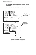
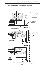
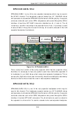
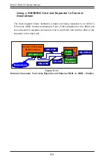
Using a RAID/HBA Card and Expander to Connect
Downstream
The block diagram below illustrates a head unit being cascaded to an SC847J
E16 series JBOD chassis downstream. Each of the backplanes in the JBOD unit
are connected to separate connectors. One to the RAID card and the other to the
expander in the head unit.
Figure E-10:
External Connector From Host Expander and External RAID to JBOD - Parallel
SMCI confidential document
8
Whitepaper
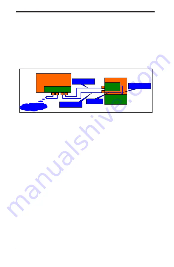
Below is block diagram of how a head unit could be cascaded to a downstream JBOD
chassis which in our case is SC847E16. Here each of the backplanes in the JBOD unit is
connected to separate connectors. One from the RAID card and the other from the
expander in the head unit.
Picture of one external connector from host’s expander and
one from Host’s external RAID to JBOD – Parallel
Figure 9
SC847E16 JBOD chassis
SFF 8088 by four
Head unit
Expander Backplane
RAID card
CBL-0108-02
CBL-0167
CBL-0166
CBL-0166
Downstream
CBL-0166
CBL-0166
CBL-0167
CBL-0108-02
Downstream
SC847J E16 Series
JBOD Chassis
Head Unit
SFF 8088 x 4
Expander
Backplane
RAID
Card
Summary of Contents for SC847E16-R1K28JBOD
Page 12: ...SC847J SAS2 Chassis Manual 1 4 Notes ...
Page 40: ...SC847J SAS2 Chassis Manual 4 2 ...
Page 45: ...4 7 Chapter 4 Chassis Setup and Maintenance Figure 4 8 Placing the System Fan ...
Page 47: ...4 9 Chapter 4 Chassis Setup and Maintenance ...
Page 48: ...SC847J SAS2 Chassis Manual 4 10 Notes ...
Page 58: ...SC847J SAS2 Chassis Manual 5 10 Notes ...
Page 64: ...SC847J SAS2 Chassis Manual B 2 Notes ...
Page 87: ...C 24 SC847J SAS2 Chassis Manual Notes ...
Page 111: ...D 24 SC847J Chassis Manual Notes ...
Page 120: ...E 9 Appendix E SC847J Chassis Internals and Externals Notes ...


