
3-1
Chapter 3: System Interface
Chapter 3
System Interface
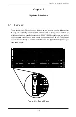
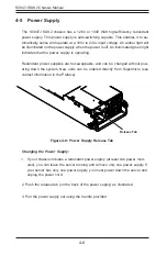
3-1 Overview
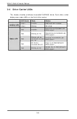
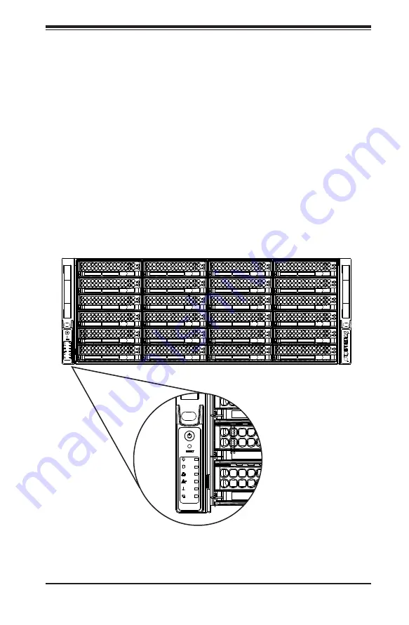
There are several LEDs on the control panel as well as others on the drive carriers
to keep you constantly informed of the overall status of the system as well as the
activity and health of specific components. SC847J SAS2 models have two buttons
on the chassis control panel: reset button and a power on/off switch. This chapter
explains the meanings of all LED indicators and the appropriate responses you
may need to take.
Figure 3-1: Control Panel
Summary of Contents for SC847E16-R1K28JBOD
Page 12: ...SC847J SAS2 Chassis Manual 1 4 Notes ...
Page 40: ...SC847J SAS2 Chassis Manual 4 2 ...
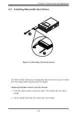
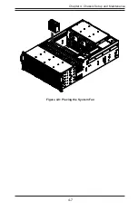
Page 45: ...4 7 Chapter 4 Chassis Setup and Maintenance Figure 4 8 Placing the System Fan ...
Page 47: ...4 9 Chapter 4 Chassis Setup and Maintenance ...
Page 48: ...SC847J SAS2 Chassis Manual 4 10 Notes ...
Page 58: ...SC847J SAS2 Chassis Manual 5 10 Notes ...
Page 64: ...SC847J SAS2 Chassis Manual B 2 Notes ...
Page 87: ...C 24 SC847J SAS2 Chassis Manual Notes ...
Page 111: ...D 24 SC847J Chassis Manual Notes ...
Page 120: ...E 9 Appendix E SC847J Chassis Internals and Externals Notes ...


