


D-4
SC847J Chassis Manual
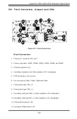
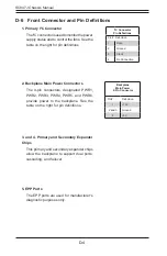
1. Primary I
2
C Connector
The I
2
C connector is used to monitor the power
supply status and to control the fans. See the
table on the right for pin definitions.
I
2
C Connector
Pin Definitions
Pin# Definition
1
Data
2
Ground
3
Clock
4
No Connection
D-6 Front Connector and Pin Definitions
Backplane
Main Power
4-Pin Connector
Pin# Definition
1
+12V
2 and 3
Ground
4
+5V
2. Backplane Main Power Connectors
The 4-pin connectors, designated PWR1,
PWR2, PWR3, PWR4, PWR5, and PWR6,
provide power to the backplane. See the
table on the right for pin definitions.
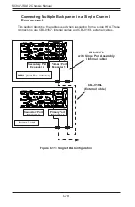
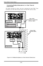
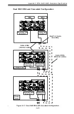
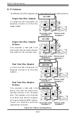
3. and 4. Primary and Secondary Expander
Chips
This primary and secondary expander chips
allow the backplane to support dual ports,
cascading, and failover.
5. EPP Ports
The EPP ports are used for manufacturer's
diagnostic purposes only.
Summary of Contents for SC847E16-R1K28JBOD
Page 12: ...SC847J SAS2 Chassis Manual 1 4 Notes ...
Page 40: ...SC847J SAS2 Chassis Manual 4 2 ...
Page 45: ...4 7 Chapter 4 Chassis Setup and Maintenance Figure 4 8 Placing the System Fan ...
Page 47: ...4 9 Chapter 4 Chassis Setup and Maintenance ...
Page 48: ...SC847J SAS2 Chassis Manual 4 10 Notes ...
Page 58: ...SC847J SAS2 Chassis Manual 5 10 Notes ...
Page 64: ...SC847J SAS2 Chassis Manual B 2 Notes ...
Page 87: ...C 24 SC847J SAS2 Chassis Manual Notes ...
Page 111: ...D 24 SC847J Chassis Manual Notes ...
Page 120: ...E 9 Appendix E SC847J Chassis Internals and Externals Notes ...


