background image

1-21

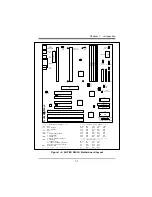
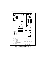
Chapter 1:  Introduction

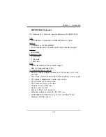
BIOS Support for USB Keyboard

If the USB keyboard is the only keyboard in the system, the USB
keyboard will work like a normal keyboard during system boot-up.

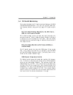
Real Time Clock Wake-up Alarm (ATX power only)

The PC is perceived to be off when not in use, but is still capable of
responding to wake-up events due to a scheduled date and time of
the month.  The user can set up a timer to wake-up or shutdown the
system at some predetermined time.

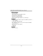
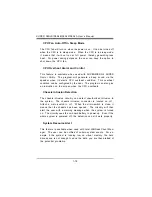
Main Switch Override Mechanism

When an ATX power supply is used, the power button can function
as a system suspend button.  When the user press on the power
button, the system will enter a SoftOff state.  The monitor will be
suspended, and the hard drive will spin down.  Pressing the power
button again will cause the whole system to wake-up.  During the
SoftOff state, the ATX power supply provides power to keep the re-
quired circuitry on the system alive.  In case the system malfunc-
tions and you want to turn off the power, just press down on the
power button for 4 seconds.  The power will turn off and no power is
provided to the motherboard.

External Modem Ring-on if System is in SoftOff State

Wake-up events can be triggered by a device such as the external
modem ringing when the system is in SoftOff state.

Summary of Contents for SUPER P6DLE

Page 1: ... SUPER SUPER P6DLS SUPER P6DLE SUPER P6SLS SUPER P6SLA USER S MANUAL Revision 1 2 ...

Page 2: ...O EVENT WILL SUPERMICRO COMPUTER BE LIABLE FOR DIRECT INDIRECT SPECIAL INCIDENTAL OR CONSEQUENTIAL DAMAGES ARISING FROM THE USE OR INABILITY TO USE THIS PRODUCT OR DOCUMENTATION EVEN IF ADVISED OF THE POSSIBILITY OF SUCH DAMAGES IN PARTICULAR THE VENDOR SHALL NOT HAVE LIABILITY FOR ANY HARDWARE SOFTWARE OR DATA STORED OR USED WITH THE PRODUCT INCLUDING THE COSTS OF THE REPAIRING REPLACING OR RECOV...

Page 3: ...ual Organization Chapter 1 Introduction describes the features specifications and performance of the SUPER P6DLS P6DLE P6SLS P6SLA system board provides detailed information about the chipset and offers warranty information Refer to Chapter 2 Installation for instructions on how to install the Pentium II processor the retention mechanism and the heat sink support This chapter provides you with the...

Page 4: ...eshooting procedures for video memo ry and the setup configuration stored in memory Instructions are also included on contacting a technical assistance support repre sentative and returning merchandise for service and the BBS for BIOS upgrades i v SUPER P6DLS P6DLE P6SLS P6SLA User s Manual ...

Page 5: ... 6 SUPER P6SLS Motherboard Layout 1 7 SUPER P6SLA Motherboard Layout 1 8 SUPER P6DLS Features 1 9 SUPER P6DLE Features 1 11 SUPER P6SLS Features 1 13 SUPER P6SLA Features 1 15 1 2 PC Health Monitoring 1 17 1 3 ACPI PC 98 Features 1 20 1 4 Chipset Overview 1 22 1 5 Wake on LAN 1 22 1 6 Power Supply 1 22 1 7 National Semiconductor Super I O 1 23 1 8 AIC 7880 SCSI Controller 1 23 1 9 Warranty Technic...

Page 6: ... the Motherboard in the Chassis 2 9 2 5 Connecting Cables 2 9 Power Supply Connectors 2 9 PW_ON Connector 2 10 Infra Red Connector 2 10 Reset Connector 2 11 Keylock Power LED Cable Connector 2 11 Hard Drive LED 2 12 Speaker Connector 2 12 SCSI LED 2 13 Power On Off State 2 13 ATX PS 2 Keyboard and Mouse Ports 2 14 Universal Serial Bus 2 14 ATX Serial Ports 2 15 SMI 2 15 CMOS Clear 2 16 External Ba...

Page 7: ... HDD 2 20 Parallel Port Connector 2 21 Floppy Connector 2 22 IDE Interfaces 2 23 SCSI Connectors 2 24 AGP Port 2 26 Chapter 3 Troubleshooting 3 1 Troubleshooting Procedures 3 1 No Video 3 1 Troubleshooting Flowchart 3 2 Memory Error 3 3 Losing the System s Setup Configuration 3 3 3 2 Technical Support Procedures 3 4 3 3 Returning Merchandise for Service 3 4 ...

Page 8: ...turer Default 1 4 Connectors Function Page J17 USB 2 14 J18 USB 2 14 J19 Printer Port 2 21 J20 COM 1 2 15 J21 COM 2 2 15 J32 ATX Power 2 9 J34 PS 2 KB and Mouse 2 14 JA1 UW SCSI 2 25 JA2 Ultra SCSI 2 24 JBT2 External Battery 2 16 JF1 IDE LED 2 12 Keylock 2 11 Speaker 2 12 JF2 IR Connector 2 10 PW_ON 2 10 Reset 2 11 JL1 Chassis Intrusion 1 14 JPA3 SCSI LED 2 13 JT1 CPU 1 Fan 2 17 JT2 CPU 2 Fan 2 17...

Page 9: ...PU and I O devices by broaden ing the bandwidth of graphics to memory It delivers a maximum of 532 MB s 2x transfer mode which is quadruple the PCI speed Wake on LAN allows remote network management and configura tion of the PC even in off hours when the PC is turned off This reduces the complexity of managing the network Other features that maximize customer satisfaction and simplicity in managin...

Page 10: ...1 2 SUPER P6DLS P6DLE P6SLS P6SLA User s Manual SUPER P6DLS Figure 1 1 SUPER P6DLS Motherboard Picture ...

Page 11: ...1 3 Chapter 1 Introduction SUPER P6DLE Figure 1 2 SUPER P6DLE Motherboard Picture ...

Page 12: ...1 4 SUPER P6DLS P6DLE P6SLS P6SLA User s Manual SUPER P6SLA Figure 1 3 SUPER P6SLA Motherboard Picture ...

Page 13: ...L1 JC3 JC2 JC1 JC4 S UPER P6DLS SCSI LED Pentium II CPU Speed M H z JB1 JB2 JB3 JB4 200 ON OFF ON ON 233 OFF OFF ON ON 266 ON ON OFF ON 300 OFF ON OFF ON 333 ON OFF OFF ON 366 OFF OFF OFF ON 400 ON ON ON OFF Bus Speed M H z JC1 JC2 JC3 50 ON ON ON 60 ON OFF OFF 66 OFF OFF OFF 75 OFF ON OFF Chassis Intrusion Thermal Control Fan SCSI Termination AGP JT1 CPU 2 FAN CPU 1 FAN Ext Battery CMOS Clear Man...

Page 14: ...SB JL1 JC3 JC2 JC1 JC4 S UPER P6DLE Pentium II CPU Speed M H z JB1 JB2 JB3 JB4 200 ON OFF ON ON 233 OFF OFF ON ON 266 ON ON OFF ON 300 OFF ON OFF ON 333 ON OFF OFF ON 366 OFF OFF OFF ON 400 ON ON ON OFF Bus Speed M H z JC1 JC2 JC3 50 ON ON ON 60 ON OFF OFF 66 OFF OFF OFF 75 OFF ON OFF Chassis Intrusion Thermal Control Fan AGP CPU 2 FAN CPU 1 FAN Ext Battery CMOS Clear Manufacturer Settings JC4 OFF...

Page 15: ...JC2 JC1 JC4 S UPER P6SLS SCSI LED Pentium II CPU Speed M H z JB1 JB2 JB3 JB4 200 ON OFF ON ON 233 OFF OFF ON ON 266 ON ON OFF ON 300 OFF ON OFF ON 333 ON OFF OFF ON 366 OFF OFF OFF ON 400 ON ON ON OFF Bus Speed M H z JC1 JC2 JC3 50 ON ON ON 60 ON OFF OFF 66 OFF OFF OFF 75 OFF ON OFF Chassis Intrusion Thermal Control Fan SCSI Termination AGP J2 is for termination CPU 2 FAN CPU 1 FAN Ext Battery CMO...

Page 16: ... CMOS Clear JC3 JC2 JC1 JC4 JB3 JB4 JB2 JB1 U27 U14 Bank1 Bank2 Bank0 1 CPU FAN JT1 U9 Manufacturer Settings JC4 OFF JL1 OFF normal ON intrusion JL2 OFF JP20 1 2 PIIX4 CTL 2 3 Save PD State default JBT1 1 2 default 2 3 CMOS Clear To clear the CMOS completely disconnect the power source WOL Wake on LAN JT1 CPU1 fan JT2 CPU2 fan JT3 Overheat fan Pentium II CPU Speed M H z JB1 JB2 JB3 JB4 200 ON OFF ...

Page 17: ... BIOS AMI Flash BIOS with boot block support DMI 2 0 Plug and Play PnP PC Health Monitoring LM78 Seven on board voltage monitors for 2 CPU cores 3 3V 5V and 12V Three fans status monitors with firmware software control on off CPU chassis temperature monitor and control CPU fan auto off in sleep mode CPU overheat control and alarm Chassis intrusion detection System resource alert Hardware BIOS viru...

Page 18: ...nism External modem ring on if system is in SoftOff state On Board I O 68 pin 16 bit Ultra Wide SCSI connector and 50 pin 8 bit Ultra SCSI connector 2 EIDE Bus Master interfaces support Ultra DMA 33 and Mode 4 1 floppy interface 2 Fast UART 16550 serial ports EPP Enhanced Parallel Port and ECP Extended Capabilities Port parallel port PS 2 mouse and PS 2 keyboard Infrared port 2 USB ports Dimension...

Page 19: ...t BIOS AMI Flash BIOS with boot block support DMI 2 0 Plug and Play PnP PC Health Monitoring LM78 Seven on board voltage monitors for 2 CPU cores 3 3V 5V and 12V Three fans status monitors with firmware software control on off CPU chassis temperature monitor and control CPU fan auto off in sleep mode CPU overheat control and alarm Chassis intrusion detection System resource alert Hardware BIOS vir...

Page 20: ...ake up alarm Main switch override mechanism External modem ring on if system is in SoftOff state On Board I O 2 EIDE Bus Master interfaces support Ultra DMA 33 and Mode 4 1 floppy interface 2 Fast UART 16550 serial ports EPP Enhanced Parallel Port and ECP Extended Capabilities Port parallel port PS 2 mouse and PS 2 keyboard Infrared port 2 USB ports Dimensions ATX 12 x 10 85 ...

Page 21: ...OS AMI Flash BIOS with boot block support DMI 2 0 Plug and Play PnP PC Health Monitoring LM78 Seven on board voltage monitors for the CPU core CPU I O 3 3V 5V and 12V Three fans status monitors with firmware software control on off CPU chassis temperature monitor and control CPU fan auto off in sleep mode CPU overheat control and alarm Chassis intrusion detection System resource alert Hardware BIO...

Page 22: ...nism External modem ring on if system is in SoftOff state On Board I O 68 pin 16 bit Ultra Wide SCSI connector and 50 pin 8 bit Ultra SCSI connector 2 EIDE Bus Master interfaces support Ultra DMA 33 and Mode 4 1 floppy interface 2 Fast UART 16550 serial ports EPP Enhanced Parallel Port and ECP Extended Capabilities Port parallel port PS 2 mouse and PS 2 keyboard Infrared port 2 USB ports Dimension...

Page 23: ...IOS AMI Flash BIOS with boot block support DMI 2 0 Plug and Play PnP PC Health Monitoring LM78 Seven on board voltage monitors for the CPU core CPU I O 3 3V 5V and 12V Three fans status monitors with firmware software control on off CPU chassis temperature monitor and control CPU fan auto off in sleep mode CPU overheat control and alarm Chassis intrusion detection System resource alert Hardware BI...

Page 24: ...wake up alarm Main switch override mechanism External modem ring on if system is in SoftOff state On Board I O 2 EIDE Bus Master interfaces support Ultra DMA 33 and Mode 4 1 floppy interface 2 Fast UART 16550 serial ports EPP Enhanced Parallel Port and ECP Extended Capabilities Port parallel port PS 2 mouse and PS 2 keyboard Infrared port 2 USB ports Dimensions ATX 12 x 8 2 ...

Page 25: ...ol On Off The PC health monitor can check the RPM status of the cooling fans The on board 3 pin CPU fan is controlled by the ACPI BIOS and the ACPI enabled operating system The thermal fans are con trolled by the overheat detection logic CPU Chassis Temperature Control The thermal control sensor will monitor the real time CPU tempera ture It will turn on the back up fan whenever the CPU temperatur...

Page 26: ...ive an indication on the screen when the CPU overheats Chassis Intrusion Detection The chassis intrusion circuitry can detect unauthorized intrusion to the system The chassis intrusion connector is located on JL1 Attach a micro switch to JL1 When the micro switch is close it means that the chassis has been opened The circuitry will then alert the user with a warning message when the system is turn...

Page 27: ... 1V to 3 5V This will allow the regulator to run cooler and make the system more stable Intel LANDesk Client Manager LDCM Support As the computer industry grows PC systems have become more complex and harder to manage Historically only experts have been able to fully understand and control these complex systems Today s users want manageable systems that interact automatically with the user Client ...

Page 28: ... power manage ment ACPI provides a generic system event mechanism for Plug and Play and an operating system independent interface for con figuration control ACPI leverages the Plug and Play BIOS data structures while providing a processor architecture independent implementation that is compatible with both Windows 95 and Win dows NT Microsoft OnNow The OnNow design initiative is a comprehensive sy...

Page 29: ... power button can function as a system suspend button When the user press on the power button the system will enter a SoftOff state The monitor will be suspended and the hard drive will spin down Pressing the power button again will cause the whole system to wake up During the SoftOff state the ATX power supply provides power to keep the re quired circuitry on the system alive In case the system m...

Page 30: ...rovides an optimized 72 bit DRAM interface 64 bit data plus ECC This interface supports 3 3V DRAM technologies The PAC provides the interface to a PCI bus operating at 33 MHz This interface implementation is compli ant with the PCI Rev 2 1 Specification The AGP interface is based on the AGP Specification Rev 1 0 It can support up to 133 MHz 532 MB s data transfer rates 1 5 Wake On LAN WOL Wake on ...

Page 31: ...ler with 16 byte FIFO Real Time Clock and an 8042 compatible keyboard con troller all in one chip The IDE interfaces provide up to Mode 4 support The two serial ports are software compatible with the Fast UART 16550 The par allel port is EPP Enhanced Parallel Port and ECP Extended Ca pabilities Port compatible including level 2 support It includes a protection circuit against damage caused when th...

Page 32: ...cturer will repair or exchange any unit or parts free of charge due to manufacturing defects for one year 12 months from the original invoice date of purchase Parts Defective parts will be exchanged or repaired within one year 12 months from the manufacturer s original invoice purchase date BIOS The manufacturer will exchange the BIOS shipping and handling excluded due to existing incompatibility ...

Page 33: ...ention mechanism attach mount under the motherboard Do this before mounting the motherboard into the chassis Do not screw too tight Mount the two black plastic pegs onto the motherboard Figure 2 1 These pegs will be used to attach the fan heatsink supports Notice that one hole and the base of one peg are larger than the other hole and peg base Push each peg into its hole firmly until you hear it c...

Page 34: ...e on the outside edge of the support If the supports are reversed the holes will not line up with the pegs on the motherboard Slide each support toward the center of the processor until the support is seated in the outside groove in the fan housing Figure 2 2 Support for Fan Heatsink Top of processor Groove in fan housing Hole and clip on outside edge ...

Page 35: ...hat the fan shroud is facing toward the pegs on the motherboard Slide the processor C into the reten tion mechanism and slide the supports onto the pegs Ensure that the pegs on the motherboard slide into the holes in the heatsink support and that the alignment notch in the SEC cartridge fits over the plug in Slot 1 Push the processor down firmly with even pres sure on both sides of the top until i...

Page 36: ... while pushing the clip forward Push the latches on the processor B outward until they click into place in the retention mechanism The latches must be secured for proper electrical connection of the processor 7 Attach the small end of the power cable C to the three pin con nector on the processor then attach the large end to the three pin connector on the motherboard Figure 2 4 Attaching the Power...

Page 37: ...n the base snaps into the motherboard Install the two pins into the base bar Insert the Pentium II with the heat sink on it into Slot 1 Install the top support bar The four top posts should be close to Slot 1 The bottommost row of fins in the heat sink should fit between the top support bar and the bottom support bar as shown in Figure 2 6 Figure 2 5 Heat Sink Support Figure 2 6 Pentium II Heat Si...

Page 38: ...h the fan heatsink supports attached until it is free from the retention mechanism 4 Remove the heatsink support pegs from the motherboard and discard them With one hand squeeze together the two halves of the peg on the bottom side of the motherboard With the other hand pull the peg out of the hole in the motherboard Do not reuse the pegs When handling the Pentium II processor avoid placing direct...

Page 39: ...ntacts When handling chips or modules avoid touching their pins Put the system board and peripherals back into their anti static bags when not in use Be sure your computer system s chassis allows excellent conductive contacts between its power supply case mounting fasteners and the system board for grounding purposes Unpacking The system board is shipped in anti static packaging to avoid static da...

Page 40: ... default bus speed is 66 MHz Table 2 1 Pentium II Speed Selection MHz JB1 JB2 JB3 JB4 200 ON OFF ON ON 233 OFF OFF ON ON 266 ON ON OFF ON 300 OFF ON OFF ON 333 ON OFF OFF ON 366 OFF OFF OFF ON 400 ON ON ON OFF Table 2 2 External Bus Speed Selection MHz JC1 JC2 JC3 50 ON ON ON 60 ON OFF OFF 66 OFF OFF OFF 75 OFF ON OFF Turbo Function There are no jumpers for turbo switch and turbo LED By default al...

Page 41: ...e chassis Therefore use as many metal fasteners as possible for better grounding 2 5 Connecting Cables Power Supply Connector After you have securely mounted the motherboard to the chassis you are ready to connect the cables Attach power supply cables to J32 for an ATX power supply See Table 2 3 for pin definitions of an ATX power supply Table 2 3 ATX Power Supply Connector Pin Definitions Connect...

Page 42: ...e power hold down the power button for at least 4 seconds See Table 2 4 for pin definitions Table 2 4 PW_ON Connector Pin Definitions Pin Number Definition 9 PW_ON 10 Ground Infrared Connector The infrared connector is located on pins 1 8 of JF2 See Table 2 5 for pin definitions Table 2 5 Infrared Pin Definitions Pin Number Definition 1 5V 2 Key 3 IRRX 4 Ground 5 IRTX 6 IRSEL0 7 IRSEL1 8 IRSEL2 ...

Page 43: ...et Pin Definitions Pin Number Definition 12 Reset 13 Ground Keylock Power LED Connector The keylock power LED connector is located on pins 5 to 9 of JF1 See Table 2 7 for pin definitions Pins 5 and 7 are for the power LED Pins 8 and 9 are for the keylock Table 2 7 Keylock Power LED Pin Definitions Pin Number Function Definition 5 Red wire LED power 6 Key No connection 7 GND Black wire 8 Keyboard i...

Page 44: ... for pin defini tions Table 2 8 Hard Drive LED Pin Definitions Pin Number Definition 1 5V 2 Key 3 HD Active 4 5V Speaker Connector The speaker connector is located on pins 10 to 13 of JF1 See Table 2 9 for pin definitions Table 2 9 Speaker Connector Pin Definitions Pin Number Function Definition 10 Red wire speaker data 11 Key No connection 12 VCC Speaker data 13 GND Black wire ...

Page 45: ...wn PD State is the default and is used when you want the system to be in power off state the first time you apply power to the system or when the system comes back from AC power failure PIIX4 control is used if you want the system to be in power on state the first time you apply power to the system or when the system comes back from AC power failure Table 2 11 JP20 Pin Definitions Connector Jumper...

Page 46: ... pin definitions Table 2 12 PS 2 Keyboard and Mouse Pin Definitions Pin Number Function 1 Data 2 NC 3 Ground 4 VCC 5 Clock 6 NC Universal Serial Bus The Universal Serial Bus is located on J17 and J18 See Table 2 13 for pin definitions Table 2 13 USB Pin Definitions Pin J17 Pin J18 Number Function Number Function 1 5V 1 5V 2 P0 2 P0 3 P0 3 P0 4 GND 4 GND 5 N A 5 Key ...

Page 47: ...Ports Pin Definitions Pin Pin Number Function Number Function 1 DCD 6 CTS 2 DSR 7 DTR 3 Serial In 8 RI 4 RTS 9 GND 5 Serial Out 10 NC SMI Refer to Table 2 15 for instructions on how to use JP19 for SUPER P6DLS P6DLE P6SLS This jumper should normally be set to 1 2 APIC SMI Table 2 15 SMI Pin Definitions Connector Jumper Number Position Function JP19 1 2 APIC SMI 2 3 PIIX4 SMI ...

Page 48: ...system then use JBT1 to clear the CMOS Do not use the PW_ON connec tor to clear the CMOS Table 2 16 CMOS Clear Pin Definitions Connector Jumper Number Position Function JBT1 1 2 Normal 2 3 CMOS Clear External Battery Connect an external battery to JBT2 Refer to Table 2 17 for pin definitions Table 2 17 External Battery Pin Definitions Pin Number Function 1 3 V 2 NC 3 NC 4 Ground ...

Page 49: ...Wake on LAN Pin Definitions Pin Number Function 1 5V Standby 2 Ground 3 Wake up Fan Connectors The thermal overheat fan is located on JT3 The CPU fans are located on JT1 and JT2 Refer to Table 2 19 for pin definitions Table 2 19 Fan Pin Definitions Pin Number Function 1 Ground 2 12 V 3 Tachometer Caution These connectors are DC direct ...

Page 50: ...ed to mix EDO DIMM modules with SDRAM DIMM modules There are no jumpers needed to configure the on board memory Memory timing requires 70ns or faster for EDO memory Refer to Figure 2 7 and the instructions below for installing or removing DIMM modules CAUTION Exercise extreme care when installing or removing the DIMM modules to prevent any possible damages DIMM Module Installation 1 Insert DIMM mo...

Page 51: ... 7 Installing Removing a DIMM Memory Module Removing DIMM Modules 1 Remove DIMM modules in any order 2 Gently push the edge of the sockets to the side to release the module Remove one side of the DIMM module first and then the other side to prevent breaking the socket To Install Insert vertically press down until it snap into place Pay attention to the two notches ...

Page 52: ...ires A wide SCSI hard disk drive requires a SCSI ribbon cable with 68 wires A single IDE hard disk drive cable has two connectors to provide for two drives To select an IDE disk drive as C you would nor mally set the drive select jumper on the drive to DS1 To select an IDE disk drive as D you would normally set the drive select jumper on the drive to DS2 Consult the documentation that came with yo...

Page 53: ...3 10 GND 11 Data Bit 4 12 GND 13 Data Bit 5 14 GND 15 Data Bit 6 16 GND 17 Data Bit 7 18 GND 19 ACJ 20 GND 21 BUSY 22 GND 23 PE 24 GND 25 SLCT 26 NC Pin Pin Number Function Number Function Parallel Port Connector The parallel port is located on J19 See Table 2 20 for pin defini tions Table 2 20 Parallel Port Pin Definitions ...

Page 54: ...itions Pin Pin Number Function Number Function 1 GND 2 FDHDIN 3 GND 4 Reserved 5 Key 6 FDEDIN 7 GND 8 Index 9 GND 10 Motor Enable 11 GND 12 Drive Select B 13 GND 14 Drive Select A 15 GND 16 Motor Enable 17 GND 18 DIR 19 GND 20 STEP 21 GND 22 Write Data 23 GND 24 Write Gate 25 GND 26 Track 00 27 GND 28 Write Protect 29 GND 30 Read Data 31 GND 32 Side 1 Select 33 GND 34 Diskette ...

Page 55: ...2 GND 3 Host Data 7 4 Host Data 8 5 Host Data 6 6 Host Data 9 7 Host Data 5 8 Host Data 10 9 Host Data 4 10 Host Data 11 11 Host Data 3 12 Host Data 12 13 Host Data 2 14 Host Data 13 15 Host Data 1 16 Host Data 14 17 Host Data 0 18 Host Data 15 19 GND 20 Key 21 DRQ3 22 GND 23 I O Write 24 GND 25 I O Read 26 GND 27 IOCHRDY 28 BALE 29 DACK3 30 GND 31 IRQ14 32 IOCS16 33 Addr 1 34 GND 35 Addr 0 36 Add...

Page 56: ...1 Table 2 23 50 pin SCSI Connector Pin Definitions Pin Pin Number Function Number Function 1 GND 26 DB 0 2 GND 27 DB 1 3 GND 28 DB 2 4 GND 29 DB 3 5 GND 30 DB 4 6 GND 31 DB 5 7 GND 32 DB 6 8 GND 33 DB 7 9 GND 34 DB P 10 GND 35 GND 11 GND 36 GND 12 Reserved 37 Reserved 13 Open 38 Termpwr 14 Reserved 39 Reserved 15 GND 40 GND 16 GND 41 ATN 17 GND 42 GND 18 GND 43 BSY 19 GND 44 ACK 20 GND 45 RST 21 G...

Page 57: ...B 14 9 GND 43 DB 15 10 GND 44 DB P1 11 GND 45 ACKB 12 GND 46 GND 13 GND 47 REQB 14 GND 48 DB 16 15 GND 49 DB 17 16 GND 50 DB 18 17 Termpwrb 51 Termpwrb 18 Termpwrb 52 Termpwrb 19 GND 53 DB 19 20 GND 54 DB 20 21 GND 55 DB 21 22 GND 56 DB 22 23 GND 57 DB 23 24 GND 58 DB P2 25 GND 59 DB 24 26 GND 60 DB 25 27 GND 61 DB 26 28 GND 62 DB 27 29 GND 63 DB 28 30 GND 64 DB 29 31 GND 65 DB 30 32 GND 66 DB 31 ...

Page 58: ...ions Pin B A 1 Spare 12V 2 5 0V Spare 3 5 0V Reserved 4 USB USB 5 GND GND 6 INTB INTA 7 CLK RST 8 REQ GNT 9 VCC3 3 VCC3 3 10 ST0 ST1 11 ST2 Reserved 12 RBF PIPE 13 GND GND 14 Spare Spare 15 SBA0 SBA1 16 VCC3 3 VCC3 3 17 SBA2 SBA3 18 SB_STB Reserved 19 GND GND 20 SBA4 SBA5 21 SBA6 SBA7 22 KEY KEY 23 KEY KEY 24 KEY KEY 25 KEY KEY 26 AD31 AD30 27 AD29 AD28 28 VCC3 3 VCC3 3 29 AD27 AD26 ...

Page 59: ...E2 AD16 40 Vddq3 3 Vddq3 3 41 IRDY FRAME 42 43 GND GND 44 45 VCC3 3 VCC3 3 46 DEVSEL TRDY 47 Vddq3 3 STOP 48 PERR Spare 49 GND GND 50 SERR PAR 51 C BE1 AD15 52 Vddq3 3 Vddq3 3 53 AD14 AD13 54 AD12 AD11 55 GND GND 56 AD10 AD9 57 AD8 C BE0 58 Vddq3 3 Vddq3 3 59 AD_STB0 Reserved 60 AD7 AD6 61 GND GND 62 AD5 AD4 63 AD3 AD2 64 Vddq3 3 Vddq3 3 65 AD1 AD0 66 SMB0 SMB1 ...

Page 60: ...2 28 SUPER P6DLS P6DLE P6SLS P6SLA User s Manual ...

Page 61: ...r Returning Merchandise for Service section s in this chapter No Video Use the following steps for troubleshooting your system configura tion 1 If you have no video remove all the add on cards and cables 2 Check for shorted connections especially under the motherboard 3 Check the jumpers settings clock speed and voltage set tings 4 Use the speaker to determine if any beep codes exist Refer to Appe...

Page 62: ...Install only the CPU memory and speaker Power On Power LED on Speaker Beeps Motherboard Good Y 8 beeps N Power Supply OK N Y Replace Power Supply Check memory BIOS and CPU Speaker Beeps Replace Motherboard Y N Figure 3 1 Troubleshooting Flowchart N Y ...

Page 63: ... 1 MB x 36 DIMMs in Banks 0 3 Determine if different speeds of DIMMs have been installed in the same or different banks and the BIOS setup is configured for the fastest speed of RAM used It is recommended to use the same RAM speed for DIMMs in different banks 4 Check for bad DIMM modules or chips Losing the System s Setup Configuration 1 Ensure that you are using a high quality power supply A poor...

Page 64: ...rd serial number Product model name Invoice number and date System configuration 3 3 Returning Merchandise for Service A receipt or copy of your invoice marked with the date of purchase is required before any warranty service will be rendered You can obtain service by calling your vendor for a Returned Merchandise Authorization RMA number When returning to the manufacturer the RMA number should be...

Page 65: ...3 5 Chapter 3 Troubleshooting ...

Page 66: ...3 6 SUPER P6DLS P6DLE P6SLS P6SLA User s Manual ...

Reviews: