


2-13
Chapter 2: Installation
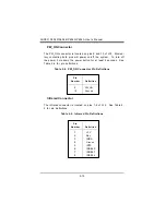
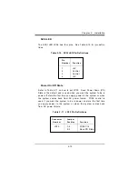
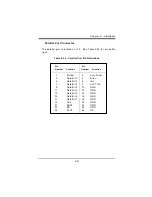
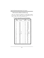
SCSI LED
The SCSI LED JPA3 has four pins. See Table 2-10 for pin defini-
tions.
Table 2-10. SCSI LED Pin Definitions
Pin
N u m b e r
Function
1
+5V
2
Control
3
Control
4
+5V
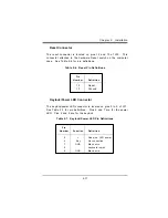
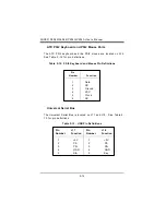
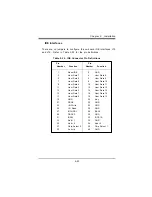
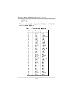
Power On/Off State
Refer to Table 2-11 on how to set JP20. Save Power Down (PD)
State is the default and is used when you want the system to be in
power off state the first time you apply power to the system or when
the system comes back from AC power failure. PIIX4 control is
used if you want the system to be in power on state the first time
you apply power to the system or when the system comes back
from AC power failure.
Table 2-11. JP20 Pin Definitions
Connector
J u m p e r
N u m b e r
Position
Function
JP20
1-2
PIIX4 Ctrl
2-3
Save PD State
Summary of Contents for SUPER P6DLE
Page 1: ... SUPER SUPER P6DLS SUPER P6DLE SUPER P6SLS SUPER P6SLA USER S MANUAL Revision 1 2 ...
Page 11: ...1 3 Chapter 1 Introduction SUPER P6DLE Figure 1 2 SUPER P6DLE Motherboard Picture ...
Page 60: ...2 28 SUPER P6DLS P6DLE P6SLS P6SLA User s Manual ...
Page 65: ...3 5 Chapter 3 Troubleshooting ...
Page 66: ...3 6 SUPER P6DLS P6DLE P6SLS P6SLA User s Manual ...


