background image

7-22

S

UPER

S

ERVER 6013L-8 Manual

7-9

Security Setup

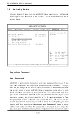
Choose Security Setup from the AMIBIOS Setup main menu.  All Security

Setup options are described in this section.  The Security Setup screen is

shown below.

Supervisor Password

User Password

AMIBIOS provides both Supervisor and User password functions. If you

use both passwords, the Supervisor password must be set first. The sys-

tem can be configured so that all users must enter a password every time

the system boots or when AMIBIOS Setup is executed, using either or both

the Supervisor password or User password. The Supervisor and User

passwords activate two different levels of password security. If you select

password support, you are prompted for a 1 – 6 character password. Type

the password on the keyboard. The password does not appear on the

screen when typed. Make sure you write it down. If you forget it, you must

clear CMOS and reconfigure. 

Remember your Password!  

Keep a record

of the new password when the password is changed. If you forget the

password, you must erase the system configuration information in CMOS.

BIOS SETUP UTILITY 

Main   Advanced   Chipset   PCIPnP  Power  Boot  Security  Exit 


Supervisor Password  : 

Not Installed 

User Password 

Not Installed 

 
>   Change Supervisor Password 
>   Change User Password 
>   Clear User Password 
Boot Sector Virus Protection 

[Disabled] 

 
Install or Change the 
password.  


 Select 

Screen 

↑↓


Select Item 

Enter   Go to Sub Screen
F1   

General Help 

F10  

Save and Exit  

ESC  

Exit 


V02.03 (C)Copyright 1985-2000, American Megatrends, Inc.


Summary of Contents for SuperServer 6013L-8

Page 1: ...SUPERSERVER 6013L 8 USER SMANUAL 1 0 SUPER...

Page 2: ...R INABILITY TO USE THIS PRODUCT OR DOCUMENTATION EVEN IF ADVISED OF THE POSSIBILITY OF SUCH DAMAGES IN PARTICULAR THE VENDOR SHALL NOT HAVE LIABILITY FOR ANY HARDWARE SOFTWARE OR DATA STORED OR USED W...

Page 3: ...apter 1 Introduction The first chapter provides a checklist of the main components included with the server system and describes the main features of the SUPER X5DLR 8G2 mainboard and the SC812 S chas...

Page 4: ...pter when adding or removing processors or main memory and when reconfiguring the motherboard Chapter 6 Advanced Chassis Setup Refer to Chapter 6 for detailed information on the 1U SC812 S rackmount s...

Page 5: ...v Preface Notes...

Page 6: ...2 1 Choosing a Setup Location 2 2 Rack Precautions 2 2 Server Precautions 2 2 2 4 Installing the SuperServer 6013L 8 into a Rack 2 3 Identifying the Sections of the Rack Rails 2 3 Installing the Chass...

Page 7: ...ting Power Cables 5 5 Connecting the Control Panel 5 6 5 4 I O Ports 5 7 5 5 Installing Memory 5 7 5 6 Adding PCI Cards 5 9 5 7 Motherboard Layout 5 10 SUPER X5DLR 8G2 Layout 5 10 SUPER X5DLR 8G2 Quic...

Page 8: ...isable 5 21 GLAN1 Enable Disable 5 21 GLAN2 Enable Disable 5 21 SCSI Enable Disable 5 22 SCSI Termination Enable Disable 5 22 PCI X Bus Speed Setting 5 22 Front Side Bus Speed 5 22 Spread Spectrum 5 2...

Page 9: ...7 AMIBIOS 7 1 Introduction 7 1 7 2 BIOS Features 7 2 7 3 Running Setup 7 2 7 4 Advanced BIOS Setup 7 4 7 5 Chipset Setup 7 15 7 6 PCI PnP Setup 7 16 7 7 Power Setup 7 18 7 8 Boot Setup 7 20 7 9 Securi...

Page 10: ...Notes SUPERSERVER 6013L 8 User s Manual x...

Page 11: ...he SuperServer 6013L 8 www supermicro com In addition to the mainboard and chassis various hardware components may have been included with your SuperServer 6013L 8 as listed below One or two 604 603 p...

Page 12: ...1 drives are supported SCA Single Connection Attach ment The SCSI drives are connected to an SCA backplane that provides power bus termination and configuration settings The SCSI drives are also hot s...

Page 13: ...l SCSI port See Figure 1 1 Cooling System The SC812 chassis revolutionary cooling design has been optimized to pro vide sufficient cooling for dual Xeon configurations The SC812 includes two heavy dut...

Page 14: ...rovides a significant boost in performance The South Bridge provides various integrated functions including the PCI to ISA bridge and support for UDMA100 security passwords and system protection Plug...

Page 15: ...er The X5DLR 8G2 features an integrated ATI video controller based on the Rage XL graphics chip Rage XL fully supports sideband addressing and AGP texturing This onboard graphics package can provide a...

Page 16: ...dress SuperMicro Computer B V Het Sterrenbeeld 28 5215 ML s Hertogenbosch The Netherlands Tel 31 0 73 6400390 Fax 31 0 73 6416525 E mail sales supermicro nl General Information support supermicro nl T...

Page 17: ...e if it was damaged in any way If the server itself shows damage you should file a damage claim with the carrier who delivered it Decide on a suitable location for the rack unit that will hold the Sup...

Page 18: ...xtending a component from the rack You should extend only one component at a time extending two or more simultaneously may cause the rack to become unstable Server Precautions Review the electrical an...

Page 19: ...should have received two rack rail assemblies with the SuperServer 6013L 8 Each of these assemblies consist of three sections an inner fixed chassis rail that secures to the 6013L 8 A and an outer fix...

Page 20: ...functions The first is to lock the server into place when installed and pushed fully into the rack which is its normal position Secondly these tabs also lock the server in place when fully extended f...

Page 21: ...ith the front of the rack rails Slide the chassis rails into the rack rails keeping the pressure even on both sides you may have to depress the locking tabs when inserting See Figure 2 3 When the serv...

Page 22: ...ou are installing the SuperServer 6013L 8 into a Telco type rack follow the directions given on the previous pages for rack installation The only difference in the installation procedure will be the p...

Page 23: ...top cover from the chassis to gain full access to the inside of the server 2 Check the CPUs processors You should have one or two processors already installed into the system board Each processor nee...

Page 24: ...e sure all power and data cables are properly connected and not blocking the chassis airflow See Chapter 5 for details on cable connec tions Also check the air seals for damage The air seals are locat...

Page 25: ...Check the SCSI disk drives Depending upon your system s configuration your system may have one or more drives already installed If you need to install SCSI drives please refer to Chapter 6 4 Check th...

Page 26: ...2 10 SUPERSERVER 6013L 8 Manual Notes...

Page 27: ...on off switch on the power supply 3 2 Control Panel Buttons There are three push button buttons located on the front of the chassis These are in order from left to right a reset button an MNI non mas...

Page 28: ...take Overheat Indicates an overheat condition in the chassis This may be caused by cables obstructing the airflow in the system or the ambient room temperature being too warm You should also check to...

Page 29: ...rive Carrier LEDs Each SCSI drive carrier has two LEDs Green When illuminated the green LED on the front of a SCSI drive carrier indicates drive activity A connection to the SCSI SCA backplane enables...

Page 30: ...n incorrect CPU has been in stalled Yellow indicates standby power is present and green indicates a full power on state There are also two surface mounted debug LEDs designated LED1 and LED2 Each is c...

Page 31: ...emory modules and the CD ROM and floppy drives When disconnecting power you should first power down the system with the operating system and then unplug the power cords of all the power supply units i...

Page 32: ...pulled into a cooling fan Remove any jewelry or metal objects from your body which are excellent metal conductors that can create short circuits and harm you if they come into contact with printed ci...

Page 33: ...use Touch a grounded metal object before removing the board from the antistatic bag Do not let components or PCBs come into contact with your clothing which may retain a charge even if you are wearing...

Page 34: ...perating Precautions Care must be taken to assure that the chassis cover is in place when the 6013L 8 is operating to assure proper cooling Out of warranty damage to the 6013L 8 system can occur if th...

Page 35: ...note that the size and weight of the mother board can cause it to bend if handled improperly which may result in dam age To prevent the motherboard from bending keep one hand under the center of the...

Page 36: ...lso do not place the motherboard on a conductive surface which can damage the BIOS battery and prevent the system from booting up 1 Lift the lever on the CPU socket Lift the lever completely or you wi...

Page 37: ...or CPU may result 6 If installing two proces sors repeat these steps to install the second processor 4 Apply the proper amount of thermal glue to the CPU die and place the heatsink fan assem bly on to...

Page 38: ...5 4 SUPERSERVER 6013L 8 User s Manual Figure 5 2 Heatsink Installation...

Page 39: ...es connect to the pin 1 locations If you are configuring the sys tem keep the airflow in mind when routing the cables The following data cables with their motherboard connector locations noted should...

Page 40: ...t even and odd numbered pins are on opposite sides of each header Make sure the red wire plugs into pin 1 as marked on the board The other end connects to the Control Panel printed circuit board locat...

Page 41: ...hat the memory is interleaved to improve performance see step 1 DIMM Installation See Figure 5 5 1 Insert the desired number of DIMMs into the memory slots starting with Bank 1 DIMM 1A DIMM 1B The mem...

Page 42: ...ion to the bottom notch To Remove Use your thumbs to gently push each release tab outward to free the DIMM from the slot Memory Support The X5DLR 8G2 only supports ECC registered PC2100 1600 DDR 266 2...

Page 43: ...ized PCI card see Figure 5 6 2 PCI card installation Before installing a PCI add on card see step 1 above Begin by swing ing the release tab on the I O backpanel shield out to the left for the PCI slo...

Page 44: ...Bank 2A Bank 1B Bank 1A Bank 0B Bank 0A D5 D8 COM2 D1 D4 South Bridge SUPER X5DLR 8G2 J12 J19 J18 IDE 2 IDE 1 FLOPPY PCI BIOS AIC 7902 Ultra III LVD SE ChA SCSI RAID SW4 Ultra III LVD SE ChB CIOB E JF...

Page 45: ...2 8 Connector Description ATX POWER Primary ATX Power Connector BANK1A BANK3B Memory RAM Slots COM1 COM2 COM1 COM2 Serial Port Connector Header CPU1 CPU2 CPU 1 and CPU2 Sockets CPU CHS OH FAN CPU Chas...

Page 46: ...ons JF1 ATX Power Connector The power supply connector meets the SSI Superset ATX 24 pin specification however it also supports a 20 pin power supply connector Make sure that the ori entation of the P...

Page 47: ...pins 9 and 10 of JF1 Attach the NIC2 LED cable to dis play network activity Refer to the table on the right for pin defini tions NIC2 LED Pin Definitions JF1 Pin Number 9 10 Definition 5V GND Overhea...

Page 48: ...ower on off the system This button can also be configured to function as a suspend button see the Power Button Mode setting in BIOS To turn off the power when set to suspend mode de press the button f...

Page 49: ...has CPU chas sis and overheat fan headers des ignated CPU CHS and OH FAN re spectively See the table on the right for pin definitions Serial Ports The COM1 serial port is located next to the USB port...

Page 50: ...able to these pins to display disk activity Refer to the table on the right for pin definitions IDE HDD LED Pin Definitions JF1 Pin Number 13 14 Definition 5V HD Active Third Power Supply Fail Header...

Page 51: ...cable from the IPMI daughter board to J20 to utilize IPMI on your system IPMB Header Pin Definitions J20 Pin Number 1 2 3 4 Definition Data Ground Clock No Connection SMB Header Pin Definitions J21 P...

Page 52: ...resent the value of the number shown beside it in the diagram Add up the numerical values of each illuminated LED in the D5 D8 row to get the high digit left and those in the D1 D4 row to get the low...

Page 53: ...GHz 1 4 GHz 1 5 GHz 1 6 GHz 1 7 GHz 1 8 GHz 1 9 GHz 2 0 GHz 2 1 GHz 2 2 GHz 2 4 GHz SW 4 ON ON ON ON ON ON SW 3 ON ON ON ON ON ON SW 1 ON ON ON ON ON ON ON ON Processor Speed Selection DIP Switch 4 5...

Page 54: ...able Disable Jumper Settings JP56 SpeakerEnable Disable To disable the onboard speaker remove the JP2 jumper See the table on the right for jumper set tings CMOS Clear JBT1 is used to clear CMOS In st...

Page 55: ...board LAN2 or NIC Network Interface Card on the motherboard See the table on the right for jumper settings The default setting is Enabled Jumper Position Pins 1 2 Pins 2 3 Definition Enabled Disabled...

Page 56: ...CSI Channel Termination Enable Disable Jumper Settings JPA1 JPA2 PCI X Bus Speed Setting Jumper P2 is used to change the speed of the single PCI X bus on the motherboard See the table on the right for...

Page 57: ...Spectrum is a technique used to stabilize operations when a system is being affected by electromagnetic interference The normal default position is open to disable Spread Spectrum See table at right f...

Page 58: ...Function 2 FDHDIN 4 Reserved 6 FDEDIN 8 Index 10 Motor Enable 12 Drive Select B 14 Drive Select A 16 Motor Enable 18 DIR 20 STEP 22 W rite Data 24 W rite Gate 26 Track 00 28 W rite Protect 30 Read Dat...

Page 59: ...MSG SEL C D REQ I O DB 8 DB 9 DB 10 DB 11 Connector Contact Number 1 2 3 4 5 6 7 8 9 10 11 12 13 14 15 16 17 18 19 20 21 22 23 24 25 26 27 28 29 30 31 32 33 34 Signal Names DB 12 DB 13 DB 14 DB 15 DB...

Page 60: ...inserting this CD into your CDROM drive the display shown in Figure 5 8 should appear If this dis play does not appear click on the My Computer icon and then on the icon representing your CDROM drive...

Page 61: ...damage to any printed circuit boards PCBs it is important to handle them very carefully The following measures are generally sufficient to protect your equipment from ESD damage Precautions Use a gro...

Page 62: ...PCB printed circuit board Make sure the red wire plugs into pin 1 on both connectors Pull all excess cabling out of the airflow path The control panel LEDs inform you of system status See Chapter 3 S...

Page 63: ...power down the system before replacing a cooling fan removing the power cord is also recommended as a safety precaution Replacing System Cooling Fans 1 Removing a fan Remove the chassis cover Detach...

Page 64: ...I drives Proceed to the next step for instructions Note You must use standard 1 high 80 pin SCA SCSI drives in the SuperServer 6013L 8 CD ROM Floppy Disk Drive For installing removing the CD ROM or fl...

Page 65: ...stall a drive into the carrier with the printed circuit board side toward the carrier so that the mounting holes align with those in the carrier Secure the drive to the carrier with four screws as sho...

Page 66: ...removal The SCSI drives are hot swap units meaning that they can be installed and removed while the system is running To remove a SCSI drive first push the colored release button located beside the dr...

Page 67: ...top cover and at the same time push the cover away from you until it stops You can then lift the top cover from the chassis to gain full access to the inside of the server With the chassis cover remo...

Page 68: ...of the chassis near the front and push the chassis top rearward about one inch To remove the failed power unit push the beige colored release tab to the right and then carefully lift the unit up about...

Page 69: ...Chapter 6 Advanced Chassis Setup 6 9 Figure 6 5 Removing Replacing the Power Supply...

Page 70: ...6 10 SUPERSERVER 6013L 8 Manual Notes...

Page 71: ...ower to the BIOS ROM enabling it to retain the system parameters Each time the computer is powered on the computer is then configured with the values stored in the BIOS ROM by the system BIOS which ga...

Page 72: ...AMIBIOS supports PC Health Monitoring chips When a failure occurs in a monitored activity AMIBIOS can sound an alarm and display a message The PC Health Monitoring chips monitor CPU temperature Chass...

Page 73: ...illustrate how to navigate through the menus Note Items displayed in gray are preset and cannot be selected Items with a blue arrow are commands not options i e Discard Changes The Main BIOS Setup Me...

Page 74: ...Configuration to go to the sub screen for that item Advanced BIOS Setup options are displayed by highlighting the option using the arrow keys All Advanced BIOS Setup options are described in this sect...

Page 75: ...n specifies the base I O port address of serial port 2 The settings for this item include Disabled 2F8 3E8 and 2E8 Serial Port 2 IRQ This option specifies the Interrupt Request address of serial port...

Page 76: ...option specifies the parallel port mode The settings for this item include Normal Bi directional EPP and ECP ECP Mode DMA Channel This option allows the user to set the setting for the ECP Mode of the...

Page 77: ...method of addressing data on a disk drive In LBA mode the maximum drive capac ity is 137 GB The settings are Disabled and Auto Select Disabled to disable LBA mode Select Auto to enable LBA mode if yo...

Page 78: ...ct UDMA0 through UDMA4 to set Ultra DMA0 through Ultra DMA4 S M A R T S M A R T stands for Self Monitoring Analysis and Reporting Technology a feature that can help predict impending drive failures Th...

Page 79: ...for the Primary IDE Master Hard Disk Write Protect This item allows the user to prevent the hard disk from being overwritten The options are Enabled or Disabled Enabled allows the drive to be used nor...

Page 80: ...3 1 2 1 44 MB 3 1 2 and 2 88 MB 3 1 2 The Enabled setting is effective only if the device is accessed through BIOS Floppy Drive Seek Use this option to Enable or Disable the floppy seek routine on boo...

Page 81: ...computer repeats a key to over 20 times per second Under normal opera tions this setting should not be changed Slow This sets the rate the computer repeats a key to under 8 times per second Primary D...

Page 82: ...tion is for enabling or disabling the internal CPU L1 cache Settings include Disabled Write Thru Write Back and Reserved Disabled This option prevents the system from using the internal CPU L1 cache T...

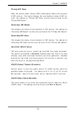
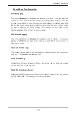
Page 83: ...following pages The screen is shown below ECC Event Logging This option Enables or Disables the logging of ECC events The events logged by AMIBIOS are post errors such as a bad BIOS floppy errors or h...

Page 84: ...ertain voltage levels and temperatures CPU1 Current Temperature CPU2 Current Temperature This reading displays the real time temperatures of CPU1 and CPU2 System Current Temperature1 System Current Te...

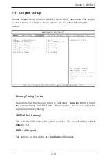
Page 85: ...tting Support Disabled DQS Selection 36 Watch Dog Timer Disabled Options for MCH Select Screen Select Item Enter Go to Sub Screen F1 General Help F10 Save and Exit ESC Exit V07 00 C Copyright 1985 200...

Page 86: ...Enabled and Disabled Auto DQS Setting Support The settings for this option are Disabled and Enabled DQS Selection This setting is preset Watchdog Timer This option is used to configure the Watchdog ti...

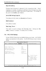
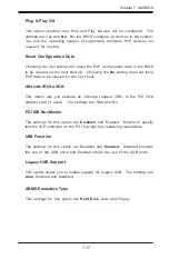
Page 87: ...n the next boot Allocate IRQ to VGA This option lets you allocate an interrupt request IRQ to the PCI VGA adapter card if used The settings are Yes and No PCI IDE BusMaster The settings for this optio...

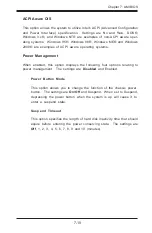
Page 88: ...are described in this section The Power Setup screen is shown below BIOS SETUP UTILITY Main Advanced Chipset PCIPnP Power Boot Security Exit ACPI Aware O S Power Management Yes Disabled Select Screen...

Page 89: ...e entering the power conserving state The settings are Off 1 2 3 4 5 6 7 8 9 and 10 minutes ACPI Aware O S This option allows the system to utilize Intel s ACPI Advanced Configuration and Power Interf...

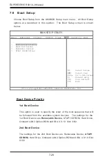
Page 90: ...or the 1st Boot Device are Removable Device ATAPI CDROM Hard Drive Onboard LAN2 Option ROM and IBA 4 0 1 9 Slot 0102 2nd Boot Device The settings for the 2nd Boot Device are Removable Device ATAPI CDR...

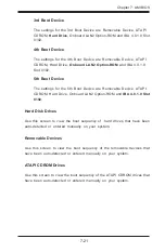
Page 91: ...he 5th Boot Device are Removable Device ATAPI CDROM Hard Drive Onboard LAN2 Option ROM and IBA 4 0 1 9 Slot 0102 Hard Disk Drives Use this screen to view the boot sequency of hard drives that have bee...

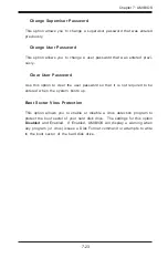
Page 92: ...rity If you select password support you are prompted for a 1 6 character password Type the password on the keyboard The password does not appear on the screen when typed Make sure you write it down If...

Page 93: ...option to clear the user password so that it is not required to be entered when the system boots up Boot Sector Virus Protection This option allows you to enable or disable a virus detection program...

Page 94: ...etup with saving the changes Select Screen Select Item Enter Go to Sub Screen F1 General Help F10 Save and Exit ESC Exit V02 03 C Copyright 1985 2000 American Megatrends Inc Exit Saving Changes Highli...

Page 95: ...system features Load Failsafe Defaults Highlighting this setting and then pressing Enter provides the safest set of parameters for the system Use them if the system is behaving errati cally Discard Ch...

Page 96: ...7 26 SUPERSERVER 6013L 8 Manual Notes...

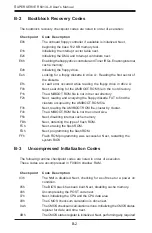
Page 97: ...y communicated through a series of audible beeps The numbers on the fatal error list on the following page correspond to the number of beeps for the corresponding error All errors listed with the exce...

Page 98: ...A 2 SUPERSERVER 6013L 8 User s Manual Notes...

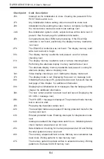
Page 99: ...e initialization code checksum will be verified D1h Initializing the DMA controller performing the keyboard controller BAT test starting memory refresh and entering 4 GB flat mode next D3h Starting me...

Page 100: ...te FAT to find the clusters occupied by the AMIBOOT ROM file F3h Next reading the AMIBOOT ROM file cluster by cluster F4h The AMIBOOT ROM file is not the correct size F5h Next disabling internal cache...

Page 101: ...llers 1 and 2 and interrupt controllers 1 and 2 13h Thevideodisplayhasbeendisabled PortBhasbeeninitialized Next initializing the chipset 14h The 8254 timer test will begin next 19h The 8254 timer test...

Page 102: ...ace checking next 34h Video display checking is over Setting the display mode next 37h The display mode is set Displaying the power on message next 38h Initializing the bus input IPL general devices n...

Page 103: ...xt 4Fh The memory size display has started The display is updated during the memory test Performing the sequential and random memory test next 50h The memory below 1 MB has been tested and initialized...

Page 104: ...s completed Checking for a locked key next 84h Locked key checking is over Checking for a memory size mismatch with CMOS RAM data next 85h The memory size check is done Displaying a soft error and che...

Page 105: ...after the Coprocessor test next 9Eh Initialization after the Coprocessor test is complete Checking the extended keyboard keyboard ID and Num Lock key next Issuing the keyboard ID command next A2h Dis...

Page 106: ...B 8 SUPERSERVER 6013L 8 User s Manual Notes...

Page 107: ...DDR DIMM sockets supporting up to 12 GB of registered ECC DDR 266 200 PC2100 1600 SDRAM DDR 266 supported if FSB is 533 MHz SCSI Controller Adaptec AIC 7902 for dual channel Ultra 320 onboard SCSI SCS...

Page 108: ...Windows NT Windows 2000 Solaris Netware SCO UNIX and Linux Dimensions 16 8 x 1 7 x 25 6 in 427 x 43 x 651 mm W x H x D Weight Net Bare Bone 30 lbs 13 6 kg Gross Bare Bone 40 lbs 18 2 kg FCC Class B EN...

Reviews: