7-12
S
UPER
S
ERVER 6015B-UR/6015B-U/6015B-NTR/6015B-NT User's Manual
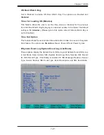
Branch 1 Rank Interleaving & Sparing
Select enable to enable the functions of Memory Interleaving and Memory Sparing
for Branch 1 Rank. The options for Memory Interleaving are 1:1, 2:1 and
4:1
. The
options for Sparing are Enabled and
Disabled
.
Enhanced x8 Detection
Select
Enabled
to enable Enhanced x8 DRAM UC Error Detection. The options
are Disabled and
Enabled
.
High Temperature DRAM Operation
When set to
Enabled, the BIOS will refer to the SPD table to set the maximum
DRAM temperature. If disabled, the BIOS will set the maximum DRAM temperature
based on a predefi ned value. The options are Enabled and
Disabled
.
AMB Thermal Sensor
Select
Enabled to activate the thermal sensor embedded in the Advanced Memory
Buffer on a fully buffered memory module for thermal monitoring. The options are
Disabled
and Enabled.
Thermal Throttle
Select Enabled to enable closed-loop thermal throttling on a fully buffered (FBD)
memory module. In the closed-loop thermal environment, thermal throttling will be
activated when the temperature of the FBD DIMM module exceeds a predefi ned
threshold. The options are Enabled and
Disabled
.
Global Activation Throttle
Select Enabled to enable open-loop global thermal throttling on a fully buffered
(FBD) memory module to make it active whenever the number of activate control
exceeds a predefi ned number. The options are Enabled and
Disabled
.
Crystal Beach Features
This feature was designed to implement Intel's I/O AT (Acceleration Technology) to
accelerate the performance of TOE devices. (A TOE device is a specialized, dedicated
processor that is installed on an add-on card or a network card to handle some or
all packet processing of the add-on card. For this motherboard, the TOE device is
built inside the ESB2 South Bridge chip.) Options are
Enabled
and Disabled.
Route Port 80h Cycles to
This feature allows the user to decide which bus to send debug information to.
The options are PCI and
LPC
.
Clock Spectrum Feature
If Enabled, the BIOS will monitor the level of Electromagnetic Interference caused
by the components and will attempt to decrease the interference whenever needed.
The options are Enabled and
Disabled
.
Summary of Contents for SUPERSERVER 6015B-NT
Page 5: ...v Preface Notes...
Page 10: ...Notes x SUPERSERVER 6015B UR 6015B U 6015B NTR 6015B NT User s Manual...
Page 25: ...Chapter 2 Server Installation 2 9 Figure 2 5 Accessing the Inside of the System...
Page 30: ...3 4 SUPERSERVER 6015B UR 6015B U 6015B NTR 6015B NT User s Manual Notes...
Page 58: ...5 24 SUPERSERVER 6015B UR 6015B U 6015B NTR 6015B NT User s Manual Notes...
Page 69: ...Chapter 6 Advanced Chassis Setup 6 11 Figure 6 6 Removing Replacing the Power Supply...
Page 70: ...6 12 SUPERSERVER 6015B UR 6015B U 6015B NTR 6015B NT User s Manual Notes...
Page 96: ...7 26 SUPERSERVER 6015B UR 6015B U 6015B NTR 6015B NT User s Manual Notes...
Page 102: ...A 6 SUPERSERVER 6015B UR 6015B U 6015B NTR 6015B NT User s Manual Notes...
Page 108: ...B 6 SUPERSERVER 6015B UR 6015B U 6015B NTR 6015B NT User s Manual Notes...
Page 122: ...C 14 SUPERSERVER 6015B UR 6015B U 6015B NTR 6015B NT User s Manual Notes...
Page 126: ...D 4 SUPERSERVER 6015B UR 6015B U 6015B NTR 6015B NT User s Manual Notes...

