5-16
S
UPER
S
ERVER 6016XT-TF/6016GT-TF/TF-TM2/TF-TC2 User's Manual
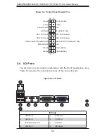
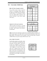
LAN1/2 (Ethernet Ports)
Two Ethernet ports (designated LAN1 and
LAN2) are located beside the VGA port
on the I/O backplane. These ports accept
RJ45 type cables.
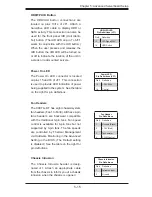
Serial Ports
A serial port is included on the I/O back-
panel. See the table on the right for pin
defi nitions.
Serial Port Pin Defi nitions
Pin # Defi nition
Pin # Defi nition
1
DCD
6
DSR
2
RXD
7
RTS
3
TXD
8
CTS
4
DTR
9
RI
5
Ground
10
NC
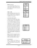
Universal Serial Bus (USB)
There are two Universal Serial Bus ports
located on the I/O panel and two additional
USB headers located on the serverboard.
The headers can be used to provide front
side USB access (cables not included).
See the table on the right for pin defi ni-
tions.
Universal Serial Bus
Pin Defi nitions
USB0/1
Pin # Defi nition
USB2/3
Pin # Defi nition
1
+5V
1
+5V
2
PO-
2
PO-
3
PO+
3
PO+
4
Ground
4
Ground
5
N/A
5
Key
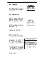
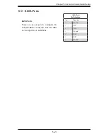
SGPIO Headers
The SGPIO (Serial General Purpose
Input/Output) headers support serial link
interfaces for the onboard SATA connec-
tors. See the table on the right for pin
defi nitions.
SGPIO Header
Pin Defi nitions
Pin# Defi nition
Pin Defi nition
1
NC
2
NC
3
Ground
4
DATA Out
5
Load
6
Ground
7
Clock
8
NC
NC = No Connection
NMI Header
Use this header to issue a non-maskable
interrupt. Refer to the table on the right for
pin defi nitions.
NMI Button
Pin Defi nitions
Pin# Defi nition
1
Control
2
Ground


