Chapter 5: Advanced Serverboard Setup
5-13
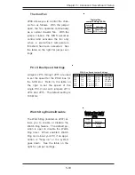
Overheat LED (OH)
Connect an LED to the OH connec-
tion on pins 7 and 8 of JF2 to pro-
vide advanced warning of chassis
overheating. Refer to the table on
the right for pin definitions.
NIC2 LED
The NIC2 (Network Interface Con-
troller) LED connection is located
on pins 9 and 10 of JF2. Attach
the NIC2 LED cable to display net-
work activity. Refer to the table
on the right for pin definitions.
Power Fail LED
The Power Fail LED connection is
located on pins 5 and 6 of JF2.
Refer to the table on the right for
pin definitions.
NIC1 LED
The NIC1 (Network Interface Con-
troller) LED connection is located
on pins 11 and 12 of JF2. Attach
the NIC1 LED cable to display net-
work activity. Refer to the table
on the right for pin definitions.
N IC1 LED Pin
Definitions
(JF2)
Pin
Number
11
12
Definition
Vcc
GN D
Overheat (OH) LED
Pin Definitions
(JF 2)
Pin
Number
7
8
Definition
Vcc
GND
Power F ail LED
Pin Definitions
(JF 2)
Pin
Number
5
6
Definition
Vcc
GND
N IC2 LED Pin
Definitions
(JF2)
Pin
Number
9
10
Definition
Vcc
GN D
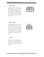
Reset Button
The connection for the system re-
set button is located on pins 3 and
4 of JF2. Refer to the table on the
right for pin definitions.
Reset Button
Pin Definitions
(JF2)
Pin
Number
3
5
Definition
Vcc
GND
Summary of Contents for SuperServer 6023P-i
Page 1: ...SUPERSERVER 6023P i USER SMANUAL 1 0b SUPER...
Page 5: ...v Preface Notes...
Page 10: ...SUPERSERVER 6023P i User s Manual x Notes...
Page 26: ...2 10 SUPERSERVER 6023P i Manual Notes...
Page 30: ...SUPERSERVER 6023P i User s Manual 3 4 Notes...
Page 58: ...5 24 SUPERSERVER 6023P i User s Manual Notes...
Page 64: ...6 6 SUPERSERVER 6023P i Manual Figure 6 3 Mounting a Drive in a Carrier...
Page 94: ...A 6 SUPERSERVER 6023P i Manual Notes...
Page 100: ...B 6 SUPERSERVER 6023P i Manual Notes...

