2-4
S
UPER
S
ERVER 7042S-i Manual
Installing the Chassis Rails:
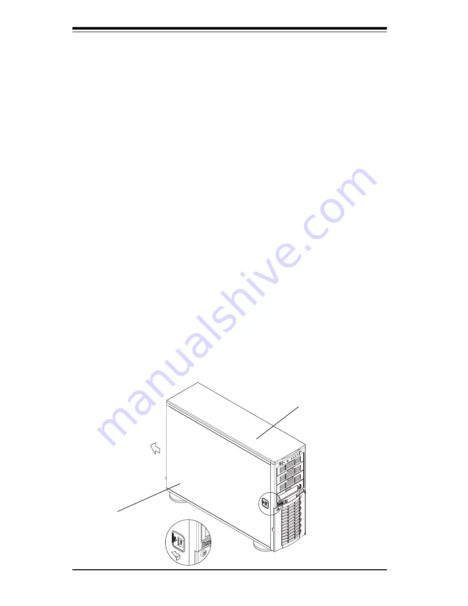
You will need to remove the top cover, the top/left cover and the feet to add
rack rails to the chassis. First, remove the top/left cover by pushing the
release tab in the center of the cover lip while pushing the cover toward
the rear of the chassis (see Figure 2-2). After the cover stops, lift it off.
Each chassis foot has a single screw. Remove the screw then depress
the foot’s locking tab from the inside of the chassis to slide the foot off.
Next, remove the top cover. You should see a release tab at the middle of
the lip. Push this tab toward the chassis edge while pushing the cover
toward the front of the chassis. It should then lift right off. You can now
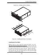
attach rack rails to the top and bottom (now the sides) of the chassis. First
add the rack handles as shown in Figure 2-3. Then position the fixed
chassis rail sections you just removed along the side of the 7042S-i making
sure the screw holes line up. Note that these two rails are left/right spe-
cific. Screw the rail securely to the side of the chassis (see Figure 2-4).
Repeat this procedure for the other rail on the other side of the chassis.
You will also need to attach the rail brackets when installing into a telco
rack.
Locking Tabs: As mentioned, both chassis rails have a locking tab,
which serves two functions. The first is to lock the server into place
when installed and pushed fully into the rack, which is its normal position.
Secondly, these tabs also lock the server in place when fully extended
from the rack. This prevents the server from coming completely out of
the rack when you pull it out for servicing.
Figure 2-2. Removing the Top/Left Cover
Top/left cover
Top cover
Summary of Contents for SuperServer 7042S-i
Page 1: ...SUPERSERVER 7042S i USER SMANUAL 1 0 SUPER...
Page 5: ...v Preface Notes...
Page 10: ...Notes SUPERSERVER 7042S i Manual x...
Page 28: ...SUPERSERVER 7042S i User s Manual 3 4...
Page 96: ...A 6 SUPERSERVER 7042S i User s Manual Notes...

