background image

Chapter 6: Advanced Chassis Setup

6-5

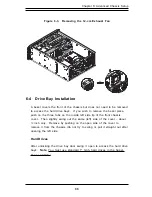
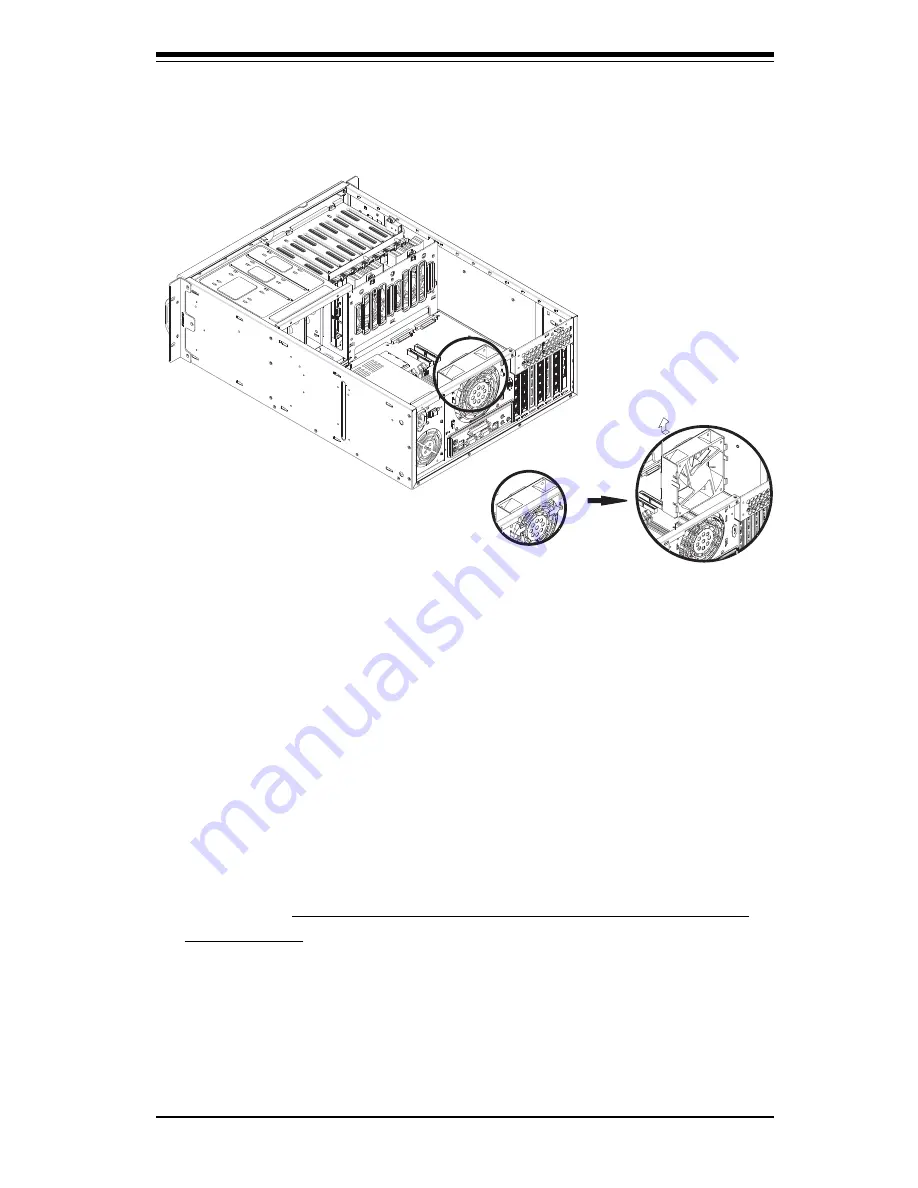
Figure 6-3.  Removing the 12-cm Exhaust Fan

6-4

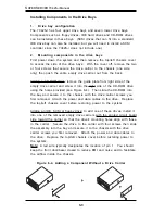
Drive Bay Installation

A bezel covers the front of the chassis but does not need to be removed

to access the hard drive bays.  If you wish to remove the bezel piece,

push on the three tabs on the inside left side lip of the front chassis

cover.  Then slightly swing out the same (left) side of the cover - about

½ inch only.  Remove by pushing on the open side of the cover to

remove it from the chassis (do not try to swing or pull it straight out after

opening the left side.

Hard Drives

After unlocking the drive bay door swing it open to access the hard drive

bays.  Note:  You must use standard 1" high, hard drives in the Super-

Server 7042S-i.

Summary of Contents for SuperServer 7042S-i

Page 1: ...SUPERSERVER 7042S i USER SMANUAL 1 0 SUPER...

Page 2: ...R INABILITY TO USE THIS PRODUCT OR DOCUMENTATION EVEN IF ADVISED OF THE POSSIBILITY OF SUCH DAMAGES IN PARTICULAR THE VENDOR SHALL NOT HAVE LIABILITY FOR ANY HARDWARE SOFTWARE OR DATA STORED OR USED W...

Page 3: ...rganization Chapter 1 Introduction The first chapter provides a checklist of the main components included with the server system and describes the main features of the SUPER P4DSE M mainboard and the...

Page 4: ...this chapter when adding or removing processors or main memory and when reconfiguring the motherboard Chapter 6 Advanced Chassis Setup Refer to Chapter 6 for detailed information on the SC742i 420 ra...

Page 5: ...v Preface Notes...

Page 6: ...paring for Setup 2 1 2 4 Installing the SuperServer 7042S i into a Rack 2 3 2 5 Checking the Motherboard Setup 2 7 2 6 Checking the Drive Bay Setup 2 9 Chapter 3 System Interface 3 1 Overview 3 1 3 2...

Page 7: ...ick Reference 5 11 5 8 Connector Definitions 5 12 ATX Power Connection 5 12 PWR_SEC Connection 5 12 Power LED 5 12 HDD LED 5 12 NIC2 LED 5 13 NIC1 LED 5 13 Overheat LED OH 5 13 Power Fail LED 5 13 Res...

Page 8: ...Parallel Port Floppy and Hard Disk Drive Connections 5 22 Parallel Port Connector 5 22 Floppy Connector 5 23 IDE Connectors 5 23 5 13 Installing Software Drivers 5 24 Chapter 6 Advanced Chassis Setup...

Page 9: ...7 6 PCI PnP Setup 7 17 7 7 Power Setup 7 19 7 8 Boot Setup 7 21 7 9 Security Setup 7 23 7 10 Exit Setup 7 25 Appendices Appendix A BIOS POST Messages A 1 Appendix B BIOS POST Codes B 1 Appendix C Syst...

Page 10: ...Notes SUPERSERVER 7042S i Manual x...

Page 11: ...he mainboard and chassis various hardware components have been included with the SuperServer 7042S i as listed below l Up to two 2 603 pin Xeon 512KB L2 cache processors l Two 2 CPU heatsinks Fan 042...

Page 12: ...l provides you with system monitor ing and control LEDs indicate network activity power supply fan failure HDD activity and SCSI drive activity The main power button a system reset button and an NMI b...

Page 13: ...B 256MB 512MB and 1GB may be used to populate the DIMM slots PC2100 is also supported but only at 200 MHz PCI Expansion Slots The P4DSE M has a total of seven PCI expansion slots consisting of three 6...

Page 14: ...ess SuperMicro Computer B V Het Sterrenbeeld 28 5215 ML s Hertogenbosch The Netherlands Tel 31 0 73 6400390 Fax 31 0 73 6416525 Email sales supermicro nl General Information support supermicro nl Tech...

Page 15: ...2 5 2 2 Unpacking the SuperServer 7042S i You should inspect the box the SuperServer 7042S i was shipped in and note if it was damaged in any way If the server itself shows damage you should file a d...

Page 16: ...extending a component from the rack You should extend only one component at a time extending two or more simultaneously may cause the rack to become unstable Server Precautions Review the electrical...

Page 17: ...ons of the Rack Rails The 7042S i rackmount kit CSE PT26 or CSE PT26B black includes two rack rail assemblies Each of these assemblies consist of three sections an inner fixed chassis rail that secure...

Page 18: ...nd bottom now the sides of the chassis First add the rack handles as shown in Figure 2 3 Then position the fixed chassis rail sections you just removed along the side of the 7042S i making sure the sc...

Page 19: ...g rail guide assemblies at the desired location in the rack keeping the sliding rail guide facing the inside of the rack Screw the assembly securely to the rack using the brackets provided Attach the...

Page 20: ...ck Do this by lining up the rear of the chassis rails with the front of the rack rails Slide the chassis rails into the rack rails keeping the pressure even on both sides you may have to depress the l...

Page 21: ...e cover from the chassis to gain full access to the inside of the server 2 Check the CPUs processors You should have one or two processors already installed into the system board Each processor should...

Page 22: ...2 8 SUPERSERVER 7042S i Manual Figure 2 6 Accessing the Inside of the SuperServer 7042S i Optional Fan...

Page 23: ...o the 5 25 drive bay To install components into the 5 25 drive bays you must first remove the top left chassis cover as described in the previous section Refer to Chapter 6 for details 3 Installing CD...

Page 24: ...stem 6 Supplying power to the system The last thing you must do is to provide input power to the system Plug the power cord from the power supply units into a high quality power strip that offers prot...

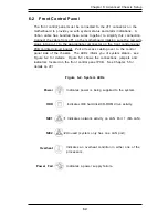
Page 25: ...utton buttons located on the front of the chassis These are in order from left to right a power on off button an NMI Non Maskable Interrupt button and a reset button l POWER This is the main power but...

Page 26: ...ains what each LED indicates when illumi nated and any corrective action you may need to take l Power Indicates external power is being supplied to the system s power supply unit This LED should norma...

Page 27: ...e installed properly see Section 5 5 and Figure 5 4 l Power Fail Indicates a power supply fan has failed The power supply will continue to operate with a secondary backup fan but will need to be repla...

Page 28: ...SUPERSERVER 7042S i User s Manual 3 4...

Page 29: ...emory modules and the CD ROM and floppy drives When disconnecting power you should first power down the system with the operating system and then unplug the power cords of all the power supply units i...

Page 30: ...fan l Remove any jewelry or metal objects from your body which are excellent metal conductors that can create short circuits and harm you if they come into contact with printed circuit boards or area...

Page 31: ...grounded metal object before removing the board from the antistatic bag l Do not let components or PCBs come into contact with your clothing which may retain a charge even if you are wearing a wrist...

Page 32: ...erating Precautions Care must be taken to assure that all chassis covers are in place when the 7042S i is operating to ensure proper cooling Out of warranty damage to the 7042S i system can occur if t...

Page 33: ...it is important to handle them very carefully see previous chapter Also note that the size and weight of the motherboard can cause it to bend if handled improperly which may result in damage To preve...

Page 34: ...Heatsink Installation When handling the processor package avoid placing direct pressure on the label area of the fan Also do not place the motherboard on a conductive surface which can damage the BIOS...

Page 35: ...the retention clips into their proper position 6 Connect the three wires of the CPU fan to the respective CPU fan connector Make sure you route the wires so they are away from the fan blades and do no...

Page 36: ...5 4 SUPERSERVER 7042S i User s Manual Figure 5 2 Heatsink Fan Installation motherboard shown is not the P4DSE M...

Page 37: ...he pin 1 locations If you are configuring the system yourself keep the airflow in mind when routing the cables The following data cables with their motherboard connector locations noted should be conn...

Page 38: ...on opposite sides of each header All JF1 wires have been bundled into single ribbon cable to simplify their connection Make sure the red wire plugs into pin 1 as marked on the board The other end conn...

Page 39: ...Memory is not interleaved so you can add any number of DIMMs into the slots in any order 2 Insert each DIMM module into its slot Note the notch at the bottom of the module to prevent inserting the mod...

Page 40: ...Slot Figure 5 4a Side View of DIMM Installation into Slot To Install Insert module vertically and press down until it snaps into place Pay attention to the bottom notches To Remove Use your thumbs to...

Page 41: ...to the PCI slot you wish to populate Insert the card into the slot on the motherboard pushing down with your thumbs evenly on both sides of the card Finish by using a screw to secure the top of the ca...

Page 42: ...5 JF2 DDR1 DDR3 DDR4 DDR2 North Bridge PCI X 1 PCI X 2 PCI X 3 PCI 4 PCI 5 PCI 6 Rage XL SW1 COM2 BIOS South Bridge IO Bridge IDE 1 IDE 2 FLOPPY J28 J24 CR1 JF1 JP13 OH CHS Fan JP15 BATTERY CPU1 Fan C...

Page 43: ...See page 2 19 Connector Description COM1 COM2 COM1 COM2 Serial Ports CPU CHS OH FAN CPU Chassis Overheat Fan Headers CPU1 CPU2 CPU 1 and CPU2 Sockets DDR1 DDR4 Memory SDRAM Slots JF1 Front Control Pan...

Page 44: ...on pins 13 and 14 of JF1 Attach the IDE hard drive LED cable to these pins to display disk activity Refer to the table on the right for pin definitions IDE HDD L ED Pin Definitions JF1 Pin Number 13 1...

Page 45: ...9 and 10 of JF1 This connection is not used on the 7042S i since there is only one LAN port O verheat O H L ED Pin Definitions JF1 Pin Number 7 8 Definition 5V GND Power Fail LED The Power Fail LED co...

Page 46: ...e system This button can also be configured to function as a suspend button see the Power Button Mode setting in BIOS To turn off the power when set to suspend mode de press the button for at least 4...

Page 47: ...s The motherboard has two CPU three Chassis and one Chassis Overheat fan headers See the table on the right for pin defini tions Serial Ports The COM1 serial port is located under the parallel port se...

Page 48: ...ke up W ake On LAN Pin Definitions JP11 Wake On LAN The Wake On LAN header is des ignated JP11 See the table on the right for pin definitions You must have a LAN card with a Wake on LAN connector and...

Page 49: ...nly avail able when using triple redundant Supermicro power supplies See the table on the right for pin defini tions Power Supply Fail Header Pin Definitions JP13 Pin Num ber 1 2 3 4 Definition P S 1...

Page 50: ...z 1 7 GHz 1 8 GHz 1 9 GHz 2 0 GHz 2 1 GHz 2 2 GHz 2 4 GHz SW 1 ON ON ON ON ON ON SW 2 ON ON ON ON ON ON SW 4 ON ON ON ON ON ON ON ON Processor Speed Selection DIP Switch 1 CR1 LED CR1 is an onboard LE...

Page 51: ...he system remove the AC power cord and then short JBT1 to clear CMOS Do not use the PW_ON connector to clear CMOS 5 11 Jumper Settings Explanation of Jumpers To modify the operation of the motherboard...

Page 52: ...per Position 1 2 2 3 Definition Enabled Disabled VGA Enable Disable Jumper Settings JP9 Watch Dog Enable JP19 is used to enable or disable the Watch Dog function This jumper is used together with the...

Page 53: ...s Note if you force the slots s to 33 MHz you must set the P1 bus speed jumper above to pins 1 2 Jum per Position Open Closed Definition Disabled 33 MHz PCI 33 M Hz PCI Enable Disable Jumper Settings...

Page 54: ...disk drives The connector with twisted wires always connects to drive A and the connector that does not have twisted wires always connects to drive B Parallel Port Connector The parallel port is locat...

Page 55: ...Select A 16 Motor Enable 18 DIR 20 STEP 22 W rite Data 24 W rite Gate 26 Track 00 28 W rite Protect 30 Read Data 32 Side 1 Select 34 Diskette Floppy Connector Pin Definitions JP28 Pin Num ber Function...

Page 56: ...rting this CD into your CD ROM drive the display shown in Figure 5 7 should appear If this display does not appear double click on the My Computer icon and then on the icon representing your CD ROM dr...

Page 57: ...nt to handle them very carefully The following measures are generally sufficient to protect your equipment from static discharge Precautions Use a grounded wrist strap designed to prevent static disch...

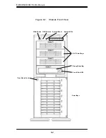
Page 58: ...6 2 SUPERSERVER 7042S i Manual Drive Bays Figure 6 1 Chassis Front View Front Bezel Lock 5 1 4 Drive Bays System Reset Main Power NMI Button System LEDs Front Side USB Floppy Drive Bay...

Page 59: ...rinted circuit board Pull all excess cabling over to the control panel side of the chassis The LEDs inform you of system status see Figure 6 2 for details Figure 6 3 shows the connections jumpers and...

Page 60: ...t swappable Replacing System Fans 1 Identifying the failed fan Inspect the back of the chassis to see if the 12 cm exhaust fan has failed You must power down the system to replace this fan To replace...

Page 61: ...he three tabs on the inside left side lip of the front chassis cover Then slightly swing out the same left side of the cover about inch only Remove by pushing on the open side of the cover to remove i...

Page 62: ...ght side of the CD ROM drive using the holes provided see Figure 6 4 Then slide the CD ROM into the bay and secure it to the chassis with the drive carrier screws you first removed Attach the power an...

Page 63: ...ack of the power supply The PWR Fail LED and the LED on the back of the power supply will also illuminate and remain on until the failed unit has been replaced Replacing the Power Supply 1 Accessing t...

Page 64: ...6 8 SUPERSERVER 7042S i Manual Figure 6 8 Chassis Rear View 420W Power Supply I O Backplane PCI Slots 7 Alarm Reset 12 cm Exhaust Fan...

Page 65: ...BIOS ROM enabling it to retain the system parameters Each time the computer is powered on the computer is then configured with the values stored in the BIOS ROM by the system BIOS which gains control...

Page 66: ...ive AMIBIOS supports PC Health Monitoring chips When a failure occurs in a monitored activity AMIBIOS can sound an alarm and display a message The PC Health Monitoring chips monitor CPU temperature Ch...

Page 67: ...illustrate how to navigate through the menus Note Items displayed in gray are preset and cannot be selected Items with a blue arrow are commands not options i e Discard Changes The Main BIOS Setup Me...

Page 68: ...rIO Configuration to go to the sub screen for that item Advanced BIOS Setup options are displayed by highlighting the option using the arrow keys All Advanced BIOS Setup options are described in this...

Page 69: ...specifies the base I O port address of serial port 2 The settings for this item include Disabled 2F8 3E8 and 2E8 Serial Port 2 IRQ This option specifies the Interrupt Request address of serial port 2...

Page 70: ...his option specifies the parallel port mode The settings for this item include Normal Bi directional EPP and ECP ECP Mode DMA Channel This option allows the user to set the setting for the ECP Mode of...

Page 71: ...method of addressing data on a disk drive In LBA mode the maximum drive capac ity is 137 GB The settings are Disabled and Auto Select Disabled to disable LBA mode Select Auto to enable LBA mode if you...

Page 72: ...elect UDMA0 trhough UDMA4 to set Ultra DMA0 through Ultra DMA4 S M A R T S M A R T stands for Self Monitoring Analysis and Reporting Technology a feature that can help predict impending drive failures...

Page 73: ...or the Primary IDE Master Hard Disk Write Protect This item allows the user to prevent the hard disk from being overwritten The options are Enabled or Disabled Disabled allows the drive to be used nor...

Page 74: ...p Boot Settings Configuration Quick Boot This option allows the BIOS to skip certain tests that are normally perfomred on boot up You can disable the option to speed up boot time The settings are Disa...

Page 75: ...ast This sets the rate the computer repeats a key to over 20 times per second Under normal opera tions this setting should not be changed Slow This sets the rate the computer repeats a key to under 8...

Page 76: ...option is for enabling or disabling the internal CPU L1 cache Settings include Disabled Write Thru Write Back and Reserved Disabled This option prevents the system from using the internal CPU L1 cach...

Page 77: ...llowing pages The screen is shown below ECC Event Logging This option Enables or Disables the logging of ECC events The events logged by AMIBIOS are post errors such as a bad BIOS floppy errors or har...

Page 78: ...e BIOS continuously monitors the health of your system by measuring certain voltage levels and temperatures CPU1 Current Temperature CPU2 Current Temperature This reading displays the real time temper...

Page 79: ...dress are copied shadowed from ROM to RAM BIOS SETUP UTILITY Main Advanced Chipset PCIPnP Power Boot Security Exit C000 16k Shadow Cached C400 16k Shadow Cached C800 16k Shadow Cached CC00 16k Shadow...

Page 80: ...within the PCI memory re gions Memory Writing Posting The settings are Enabled and Disabled Scrubbing Enable The settings are Enabled and Disabled Scrubbing writes corrected ECC data back into memory...

Page 81: ...abled 2 minutes 5 minutes 10 minutes and 15 minutes BIOS SETUP UTILITY Main Advanced Chipset PCIPnP Power Boot Security Exit Plug Play O S Reset Config Data PCI Latency Timer Allocate IRQ to VGA Pale...

Page 82: ...24 and 248 PCI clocks Allocate IRQ to PCI VGA This option lets you allocate an interrupt request IRQ to the PCI VGA adapter card if used The settings are Yes and No Palette Snooping When enabled this...

Page 83: ...r Legacy USB The settings are Auto Enabled and Disabled ARMD Emulation Type This settings for this option are Hard Disk Auto and Floppy BIOS SETUP UTILITY Main Advanced Chipset PCIPnP Power Boot Secur...

Page 84: ...re before entering the power conserving state The settings are Off 1 2 3 4 5 6 7 8 9 and 10 minutes ACPI Aware O S This option allows the system to utilize Intel s ACPI Advanced Configuration and Powe...

Page 85: ...settings for the 1st Boot Device are Removable Device ATAPI CDROM Hard Drive and Intel UNDI PXE 2 0 build 082 2nd Boot Device The settings for the 2nd Boot Device are Removable Device ATAPI CDROM Har...

Page 86: ...d Intel UNDI PXE 2 0 build 082 Hard Disk Drives Use this screen to view the boot sequency of hard drives that have been auto detected or entered manually on your system Removable Devices Use this scre...

Page 87: ...f you select password support you are prompted for a 1 6 character password Type the password on the keyboard The password does not appear on the screen when typed Make sure you write it down If you f...

Page 88: ...Use this option to clear the user password so that it is not required to be entered when the system boots up Boot Sector Virus Protection This option allows you to enable or disable a virus detection...

Page 89: ...ith saving the changes Select Screen Select Item Enter Go to Sub Screen F1 General Help F10 Save and Exit ESC Exit V02 03 C Copyright 1985 2000 American Megatrends Inc Exit Saving Changes Highlighting...

Page 90: ...ces and system features Load Failsafe Defaults Highlighting this setting and then pressing Enter provides the safest set of parameters for the system Use them if the system is behaving errati cally Di...

Page 91: ...ed Keyboard controller failed test May require replacing keyboard controller Keyboard locked Unlock key switch Unlock the system to proceed Monitor type does not match CMOS Run SETUP Monitor type not...

Page 92: ...ous POST did not complete successfully POST loads default values and offers to run Setup If the failure was caused by incorrect values and they are not corrected the next boot will likely fail On syst...

Page 93: ...tware NMI Failed ServerBIOS2 test error Cannot generate software NMI Non Maskable Interrupt Fail Safe Timer NMI Failed ServerBIOS2 test error Fail Safe Timer takes too long device Address Conflict Add...

Page 94: ...sfully tested nnnn kB System RAM Passed Where nnnn is the amount of system RAM in kilobytes successfully tested One or more I2O Block Storage Devices were excluded from the Setup Boot Menu There was n...

Page 95: ...Write down and follow the information shown on the screen Press F2 to enter Setup Optional message displayed during POST Can be turned off in Setup PS 2 Mouse PS 2 mouse identified Run the I2O Configu...

Page 96: ...A 6 SUPERSERVER 7042S i User s Manual Notes...

Page 97: ...port 80h attempt to initialize video and write the error in the top left corner of the screen The following is a list of codes that may be written to port 80h Appendix B BIOS POST Codes POSTCode Descr...

Page 98: ...dow 32h Test CPU bus clock frequency 33h Initialize Phoenix Dispatch Manager 36h Warm start shut down 38h Shadow system BIOS ROM 3Ah Auto size cache 3Ch Advanced configuration of chipset registers 3Dh...

Page 99: ...are interrupt vectors 7Dh Initialize Intelligent System Monitoring 7Eh Initialize coprocessor if present 80h Disable onboard Super I O ports and IRQs 81h Late POST device initialization 82h Detect and...

Page 100: ...rm RomPilot about the end of POST B2h POST done prepare to boot operating system B4h 1 One short beep before boot B5h Terminate QuietBoot optional B6h Check password optional B7h Initialize ACPI BIOS...

Page 101: ...tialize PIC and DMA ECh Initialize Memory type EDh Initialize Memory size EEh Shadow Boot Block EFh System memory test F0h Initialize interrupt vectors F1h Initialize Run Time Clock F2h Initialize vid...

Page 102: ...B 6 SUPERSERVER 7042S i User s Manual Notes...

Page 103: ...supermicro com TechSupport htm Chipset Intel E7500 Plumas chipset BIOS 4 Mb Phoenix Flash ROM Memory Capacity Six 184 pin DDR DIMM sockets supporting up to 4 GB of registered ECC PC1600 DDR 200 SDRAM...

Page 104: ...able One 1 12 cm exhaust fan not hot swappable Operating Environment Operating Temperature Range 0 to 35 degrees C Humidity Range 5 90 non condensing Motherboard Model P4DSE M Form Factor Full ATX Dim...

Reviews: