background image

R

R

R

10 1/32 

 (255.0)

(4) Places

10 1/4 

 (254.4)

(299.7)

10 

11 13/16

(260.0)

3/8 - 16 Thd.

2 1/16 

(114.0)

1 1/4 

4 1/2

A

B

C

(31.8)

(52.0)

F

(16) Places

SAE #10 Ports

4 1/2 

6 3/4 

(162.6)

1/2 - 13 Thd.

D

E

(171.2)

(114.3)

6 13/32 

 (255.0)

10 1/32 

(4) Places

SAE #4 Port

(260.0)

10 1/4 

3/8 - 16 Thd.

C

B

A

(16) Places

(114.3)

(171.2)

6 3/4 

4 1/2 

6 13/32 

(162.6)

E

D

(52.0)

1/2 - 13 Thd.

2 1/16 

4 1/2

(114.0)

(31.8)

1 1/4 

G

SAE #10 Ports

F

G

4

H11P

NOTES:

1. All values are

based on actual
winch test data and
measurements.

2. Line speed is based

on standard 4 inch,
(101.6 mm), drum
dia. with 7/16 dia.,
(11 mm), wire rope.

3. Drum capacity is

based on standard
4 inch, (101.6 mm),
drum dia. with 7/16
dia., (11 mm), wire
rope, value of K=.9.

4. Approximate values

of line pull and line
speed not listed
may be found by
interpolation. 

Layer 1

Layer 2

Layer 3

Layer 4

Layer 5

Layer 6

Psi

Bar

Lbs.

Kgs

Lbs.

Kgs

Lbs.

Kgs

Lbs.

Kgs

Lbs.

Kgs

Lbs.

Kgs

1,000 69.0 6,600 2994 5,800 2631 5,000 2268 4,300 1950 4,000 1814 3,750 1701

1,500 103.4 9,500 4309 8,300 3765 7,300 3311 6,600 2994 5,900 2676 5,500 2495

2,000 138.0 12,400 5625 10,500 4763 9,600 4354 8,600 3901 7,700 3493 7,200 3266

Gal.

Lit.

Ft. Meter Ft. Meter Ft. Meter Ft. Meter Ft. Meter Ft. Meter

Min. Min. Min. Min. Min. Min. Min. Min. Min. Min. Min. Min. Min. Min.

7

26.5

17.0

5.2

18.8

5.7

21.0

6.4

25.0

7.6

26.0

7.9

28.5

8.7

11

41.6

24.3

7.4

30.5

9.3

35.3

10.7

41.0

12.5

43.0

13.1

48.3

14.7

15

57.0

38.3

11.7

43.0

13.1

49.0

14.9

57.0

17.4

61.0

18.6

66.5

20.3

Length

In.

MM.

Ft. Meter Ft. Meter Ft. Meter Ft. Meter Ft. Meter Ft. Meter

10.0

229

24

7.3

53

16.2

86

26.2

124

37.8

167

50.9

214

65.2

11.4

254

29

8.8

63

19.2

103

31.4

149

45.4

200

60.9

257

78.3

Line Pull

Line Speed

Drum

Capacity

H13P

NOTES:

1. All values are

based on actual
winch test data and
measurements.

2. Line speed is based

on standard 4 inch,
(101.6 mm), drum
dia. with 7/16 dia.,
(11 mm), wire rope.

3. Drum capacity is

based on standard
4 inch, (101.6 mm),
drum dia. with 7/16
dia., (11 mm), wire
rope, value of K=.9.

4. Approximate values

of line pull and line
speed not listed
may be found by
interpolation. 

Layer 1

Layer 2

Layer 3

Layer 4

Layer 5

Layer 6

Psi

Bar

Lbs.

Kgs

Lbs.

Kgs

Lbs.

Kgs

Lbs.

Kgs

Lbs.

Kgs

Lbs.

Kgs

1,000 69.0 8,000 3629 6,700 3039 5,900 2676 5,300 2404 4,800 2177 4,500 2041

1,500 103.4 11,400 5171 10,000 4536 9,000 4082 8,200 3719 7,200 3266 6,700 3039

2,000 138.0 14,200 6441 12,800 5806 11,500 5216 10,600 4808 9,200 4173 8,400 3810

Gal.

Lit.

Ft. Meter Ft. Meter Ft. Meter Ft. Meter Ft. Meter Ft. Meter

Min. Min. Min. Min. Min. Min. Min. Min. Min. Min. Min. Min. Min. Min.

7

26.5

12.8

3.9

15.5

4.8

17.8

5.4

19.5

5.9

21.5

6.6

23.0

7.0

11

41.6

20.0

6.1

24.5

7.5

27.0

8.2

32.0

9.8

34.5

10.5

37.5

11.4

15

57.0

30.3

9.2

33.0

10.1

39.0

11.9

44.0

13.4

51.0

15.5

56.0

17.1

Length

In.

MM.

Ft. Meter Ft. Meter Ft. Meter Ft. Meter Ft. Meter Ft. Meter

10.0

229

24

7.3

53

16.2

86

26.2

124

37.8

167

50.9

214

65.2

11.4

254

29

8.8

63

29.2

103

31.4

149

45.4

200

60.9

257

78.3

Line Pull

Line Speed

Drum

Capacity

H15P

NOTES:

1. All values are

based on actual
winch test data and
measurements.

2. Line speed is based

on standard 4 inch,
(101.6 mm), drum
dia. with 1/2 dia.,
(11 mm), wire rope.

3. Drum capacity is

based on standard
4 inch, (101.6 mm),
drum dia. with 1/2
dia., (12 mm), wire
rope, value of K=.9.

4. Approximate values

of line pull and line
speed not listed
may be found by
interpolation. 

Layer 1

Layer 2

Layer 3

Layer 4

Layer 5

Psi

Bar

Lbs.

Kgs

Lbs.

Kgs

Lbs.

Kgs

Lbs.

Kgs

Lbs.

Kgs

1,000 69.0 8,000 3629 7,300 3311 6,400 2903 5,800 2631 5,300 2404

1,500 103.4 12,000 5443 11,200 5080 9,500 4309 8,500 3855 7,400 3357

2,000 138.0 15,000 6804 13,500 6123 12,000 5443 10,800 4899 9,800 4445

Gal.

Lit.

Ft. Meter Ft. Meter Ft. Meter Ft. Meter Ft. Meter

Min. Min. Min. Min. Min. Min. Min. Min. Min. Min. Min. Min.

7

26.5

10.0

3.0

14.5

4.4

15.5

4.7

17.0

5.2

20.0

6.1

11

41.6

18.5

5.6

23.0

7.0

25.0

7.6

30.0

9.1

32.0

9.8

15

57.0

27.0

8.2

33.0

10.1

37.0

11.3

42.0

12.8

47.0

14.3

Length

In.

MM.

Ft. Meter Ft. Meter Ft. Meter Ft. Meter Ft. Meter

10.0

229

21

6.4

47

14.3

78

23.8

113

34.4

153

46.6

11.4

254

25

7.6

56

17.1

93

28.3

136

41.5

184

55.1

Line Pull

Line Speed

Drum

Capacity

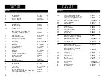
P E R F O R M A N C E

M O U N T I N G

S P E C I F I C A T I O N S

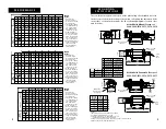
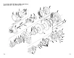
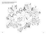
These winches may be mounted on a flat plate using the threaded holes in
the bottom of the winch castings or between rails using the threaded holes
in the sides of the winch castings. See the following diagrams for hole sizes
and locations. 

Models With Manual Freespool:
5364, 5366, 5370, 5372, 5374, 5376

5

6 3/4

(171.2)

4 1/2

(114.3

)

6 13/32

(162.6)

D

E

G

F

SAE 

#10

Ports

M12 x 1.75 Thd.

(16) Places

SAE #4 Port

(For Pneumatic

Freespool)

10 1/32

(255.0)

10 1/4

(260.0)

M10 x 1.5 Thd.

(4) Places

M10 x 1.5 Thd.

(4) Places

A

B

C

1 1/4

(31.8)

4 1/2

(114.0)

2 1/16

(52.0)

6 3/4

(171.2)

4 1/2

(114.3)

6 13/32

(162.6)

D

E

G

F

M12 x 1.75 Thd.

(16) Places

SAE

#10

Ports

NOTES:
1. Mounting bolts must be grade 8.8 or better.
2. Torque mounting bolts to 75 Ft. Lb.
3. Lengths given in above chart allow for use of

one flat washer and Helical lock washer.

4. Limit air supply to 40 psi min. 80 psi max. going to frespool clutch.
5. Dimensions are in inches (millimeters).

10” Drum

11.4” Drum

A

10 1/32 (255.0)

11 13/32 (290.0)

B

12 15/32 (317.0)

13 27/32 (352.0)

C

14 1/8 (359.0)

15 1/2 (394.0)

D

11 15/16 (303.5)

13 5/16 (338.5)

F

E

14 1/2 (368.5)

15 7/8 (403.5)

H11P

6 23/32 (170.0) G

27 5/8 (702.0)

29 (737.0)

H13P

6 7/8 (175.0)

G

27 25/32 (707.0)

29 5/32 (740.6)

H15P

6 15/16 (180.0) G

27 27/32 (712.0)

29 7/32 (742.2)

Mount

Side

Foot

Material

Bolt

Bolt

Thickness

Length

Length

1/4 ”

30mm

-

5/16 ”

30mm

-

3/8 ”

30mm

-

1/2 “

35mm

40mm

1 “

50mm

50mm

Models With Pneumatic Freespool:
5365, 5367, 5371, 5373, 5375, 5377

Summary of Contents for H11P

Page 1: ...on d opération ou de maintenance fournies par Superwinch y compris mais sans s y limiter soumettre le Produit à des charges dépassant la charge indiquée dans le Mode d Emploi ou dans les instructions pour le Produit en particulier ainsi que le numéro de modèle 3 l utilisation commerciale ou industrielle 4 l altération ou la modifica tion par des parties autres que Superwinch 5 la mauvaise utilisat...

Page 2: ...ontal or vertical configuration The H11 13 15P winches are not intended or approved for lifting hoisting or the transportation of people D E S C R I P T I O N 2 Drum Length Freespool Model 10 11 4 Man Pneu H11P H13P H15P 5364 X X X 5365 X X X 5366 X X X 5367 X X X 5370 X X X 5371 X X X 5372 X X X 5373 X X X 5374 X X X 5375 X X X 5376 X X X 5377 X X X Max Rated Line Pull H11P H13P H15P 1st Layer 11...

Page 3: ...3 4 51 0 15 5 56 0 17 1 Length In MM Ft Meter Ft Meter Ft Meter Ft Meter Ft Meter Ft Meter 10 0 229 24 7 3 53 16 2 86 26 2 124 37 8 167 50 9 214 65 2 11 4 254 29 8 8 63 29 2 103 31 4 149 45 4 200 60 9 257 78 3 Line Pull Line Speed Drum Capacity H15P NOTES 1 All values are based on actual winch test data and measurements 2 Line speed is based on standard 4 inch 101 6 mm drum dia with 1 2 dia 11 mm ...

Page 4: ... assuming a 15 to 20 line loss 1 The intermittent ratings of 20 GPM and 2250 psi must not occur simultaneously The winch motor will be damaged 2 If the hydraulic system powering the winch is capable of delivering higher flows and pressures than the winch rating installation of a separate flow control and relief valve to protect the winch circuit is required The winch may be used with hydraulic sys...

Page 5: ...tricting orifice to protect the motor 8 THIS SECTION DEALS WITH THE OPERATION OF THE WINCH AND PERFORMING A WINCHING OPERA TION READ AND FOLLOW THE INSTRUCTIONS AND WARNINGS CAREFULLY The responsibil ity for safe operation of the winch and preven tion of personal injury and property damage ultimately rests with you the operator There is no substitute for the use of good judgement and caution in op...

Page 6: ...sm engages into the up position The wire rope may now be pulled from the drum 2 To re engage the winch s drive grasp the freespool handle pull the trigger and lower the handle If the handle does not go all the way down do not force it This means the splined shaft is not lined up for proper engagement Use the directional control valve to power the winch enough to just move the drum The splined shaf...

Page 7: ...TIONS THESE WARNINGS AND PRECAU TIONS MUST BE OBSERVED AT ALL TIMES 1 Before installing or operating the winch read this manual Do not allow anyone to operate the winch until they have read this manual and received proper instruction in the winch s use If you do not understand any of the warnings or instructions call Superwinch at the number s found in the front of this manual 2 Do not operate the...

Page 8: ...ll connections and fitting for leaks THE FOLLOWING ITEMS SHOULD BE CHECKED MONTHLY A WEEK LY INSPECTION OF THESE ITEMS SHOULD BE PERFORMED ON WINCHES IN FREQUENT USE Check the brake Follow the guide lines listed in the section of this manual describing the brake Page 12 T R O U B L E S H O O T I N G A N D M A I N T E N A N C E G U I D E 14 After 50 hours of winching or annually Change gearbox grea...

Page 9: ... leak Check port for blockage Disassemble and inspect brake 2 Winch is improperly 2 Check mount see mounted mounting section in this manual 3 Not enough pressure 3 Check pump and relief valve settings Drum will not rotate 1 Brake not unlocking 1 Same as above under load 2 Freespool not engaged 2 Engage freespool 3 Damaged drive system 3 Teardown and inspect winch Winch runs too slow 1 Brake is not...

Page 10: ...2 13 14 1 2 15 65 64 60 63 62 61 60 59 58 34 35 42 43 Parts List For H11 13 15P Winches With Pneumatic Clutch Models 5365 5367 5371 5373 5375 5377 19 16 17 18 20 19 26 27 36 37 35 34 41 40 39 38 44 45 46 47 48 49 2 51 57 54 53 52 ...

Page 11: ...Winches With Manual Clutch Models 5364 5366 5370 5372 5374 5376 3 4 5 6 7 8 13 14 1 2 15 21 23 24 25 28 34 35 42 43 22 2 30 33 32 31 9 10 11 10a 12 21 16 17 18 20 19 26 27 36 37 35 34 41 40 39 38 44 45 46 47 48 49 2 51 57 54 53 52 ...

Page 12: ...1 5374 5375 11 4 Long Drum Assembly 53 90151 1 Models 5366 5367 5372 5373 5376 5377 Reference Number Description Part Number Qty H 1 1 1 3 1 5 P PA R T S L I S T 22 Reference Number Description Part Number Qty 23 37 Socket Head Set Screw M8 x 10 NA 1 38 Tie Bar 10 Long Drum Models 53 52265 2 5364 5365 5370 5371 5374 5375 Tie Bar 11 4 Long Drum Models 53 52266 2 5366 5367 5372 5373 5376 5377 39 M12...

Page 13: ...delivery of the Product by Superwinch to its authorized distributor If any model or sample was shown to Buyer such model or sample was used for illustrative purposes only and shall not be construed as a warranty that the Product shall conform to the sample or model TO THE FULLEST EXTENT PERMITTED BY APPLICABLE LAW THE FOLLOWING ARE HEREBY EXCLUDED AND DISCLAIMED 1 All warranties with respect to th...

Page 14: ...dad 13 Guía de identificación de problemas y mantenimiento 14 Mantenimiento de rutina 14 Lubricación 15 Identificación de problemas en el sistema hidráulico 15 Identificación de problemas en el cabrestante 17 Lista de piezas 18 Garantía limitada de Superwinch 24 Los cabrestantes H11 H13 H15P son unidades accionadas hidráulicamente y desarrol lan una fuerza nominal SAE J 706 de 11 000 13 000 y 15 0...

Page 15: ...gal lit pies meter pies meter pies meter pies meter pies meter pies meter min min min min min min min min min min min min min min 7 26 5 17 0 5 2 18 8 5 7 21 0 6 4 25 0 7 6 26 0 7 9 28 5 8 7 11 41 6 24 3 7 4 30 5 9 3 35 3 10 7 41 0 12 5 43 0 13 1 48 3 14 7 15 57 0 38 3 11 7 43 0 13 1 49 0 14 9 57 0 17 4 61 0 18 6 66 5 20 3 Long pulg mm pies meter pies meter pies meter pies meter pies meter pies me...

Page 16: ...el cabrestante resul ta afectado en forma considerable 4 La válvula de 4 vías puede estar equipada de una válvula integral de alivio FILTRACIÓN El sistema hidráulico debe contar en el conducto de retorno con un filtro de 10 a 40 micrones de tamaño nominal FLUIDO HIDRÁULICO Puede emplearse cualquier fluido de alto grado a base de petróleo de protección contra desgaste con vis cosidad nominal mínima...

Page 17: ... psi 15 gal min 4 Válvula de control direccional 4 vías carrete de centro flotante centrada por resorte y con válvula integral de alivio Se requiere cap nom de 2 500 psi y 15 gal min Nota Pueden utilizarse carretes de centro abierto con las mismas especificaciones 5 Colector múltiple dos válvulas para control de carga con válvula integral de doble efecto Presión nom mín de 3 000 psi controles de c...

Page 18: ...sa que no sea el aparejo aprobado F No enganche el cable a sí mismo Utilice una eslinga o cadena para abrazar la carga G Siempre protéjase las manos con guantes de cuero o al menos que tengan las palmas de cuero al manejar el cable Nunca permita que el cable se le deslice por las manos En lugar de eso efectúe un movimiento de pase de mano a mano para avanzar el cable CARRETE LIBRE El carrete libre...

Page 19: ...una presión inferior a 1 700 psi 117 bar significa que el freno está desgastado o necesita servicio PRECAUCIÓNES GENERALES ESTAS ADVERTENCIAS Y MEDIDAS DE PRECAUCIÓN DEBEN OBSER VARSE EN TODO MOMENTO 1 Antes de instalar o utilizar el cabrestante lea este manual No permita que nadie utilice el cabrestante hasta que haya leído el manual y reciba la capacitación adecuada en el uso de la unidad Si no ...

Page 20: ...del cable así como de la operación de tiro misma Mantenga a los circunstantes lejos del área de la operación Utilice el cabrestante teniendo una vista clara y sin obstrucción de la operación de tiro Siempre esté conciente de los posibles peligros Pregúntese Qué pasaría si se rompiera el cable o alguno de los aparejos 7 Para facilitar el tiro de carga no mueva el vehículo que tiene mon tado el cabr...

Page 21: ...ito hidráulico para ver si tiene fugas o compo nentes descompuestos 1 Revise la posición de la palanca 2 Revise el montaje vea la sección sobre monta je de este manual 1 Apriete el conector 2 Cambie el motor 1 Desarme el freno y repárelo 1 Instale un conducto de retorno por separado 1 Engrane bien y enclave el mecanismo de car rete libre B El sistema funciona en forma errática 1 Aire presente en e...

Page 22: ... 15 65 64 60 63 62 61 60 59 58 34 35 42 43 16 17 18 20 19 26 27 36 37 35 34 41 40 39 38 44 45 46 47 48 49 2 51 57 54 53 52 43 42 Lista de piezas de los cabrestantes H11 H13 H15P con embrague neumático Modelos 5365 5367 5371 5373 5375 5377 ...

Page 23: ...28 34 35 42 43 22 2 30 33 32 31 9 10 11 10a 12 16 17 18 20 19 26 27 36 37 35 34 41 40 39 38 44 45 46 47 48 49 2 51 57 54 53 52 44 Lista de piezas de los cabrestantes H11 H13 H15P con embrague manual Modelos 5364 5366 5370 5372 5374 5376 45 ...

Page 24: ...3 0815022 6 2 Rondana de presión M8 4 51 0823 16 3 Tapa de la caja de engranajes 53 25054 1 4 Almohadilla de empuje 1ª etapa 53 52224 1 5 Engrane anular 1ª etapa 88 32288 01 1 6 Conjunto del portador 1ª etapa 53 90270 1 7 Engrane solar 2ª etapa 53 54033 1 8 Espaciador del engrane anular 53 50421 1 9 Engrane solar 1ª etapa 53 54036 1 10 Acoplamiento de la flecha impulsora 53 70032 1 10a Espaciador ...

Page 25: ...nual del Propietario o las instrucciones para un Producto y número de modelo en particular 3 uso comercial o indus trial 4 alteración o modificación por terceros que no son Superwinch 5 mal uso abuso negligencia accidente casos fortuitos o terrorismo o 6 otras causas que escapan al con trol de Superwinch después de que Superwinch o su distribuidor autorizado hayan entrega do el Producto Si se le m...

Page 26: ...inage libre 10 Frein à sécurité positive 12 Renseignements sur la sécurité 13 Guide de détection des problèmes et d entretien 14 Entretien régulier 14 Lubrification 15 Guide de détection des problèmes pour le système hydraulique 15 Guide de détection des problèmes pour le treuil 17 Liste de pièces 18 Garantie limitée du Superwinch 24 Les treuils H11 13 15P sont des treuils à entraînement hydrauliq...

Page 27: ...se du câble est basée sur un diamètre de tambour standard de 4 po 101 6 mm avec un câble métallique de 7 16 de diamètre 11 mm 3 La capacité du tambour est basée sur un diamètre de tambour standard de 4 po 101 6 mm avec un diamètre de câble de 7 16 11 mm valeur K 0 9 4 Des valeurs de traction de câble et de vitesse de câble approximatives peuvent être trouvées par interpolation pour celles qui ne s...

Page 28: ...le réduira énormément la per formance du treuil 4 La vanne à quatre directions peut être équipée d une soupape de sûreté intégrée FILTRAGE Le système hydraulique devrait être équipé d un filtre sur la ligne de retour ayant une valeur nominale de 10 à 40 microns FLUIDE HYDRAULIQUE Tout fluide hydraulique de classe élevée anti usure et à base de pét 55 EXIGENCES DU SYSTÈME HYDRAULIQUE COMPOSANTS CIR...

Page 29: ...TS 1 Réservoir de 25 gal min recommandé 2 Filtre d aspiration valeur nominale de 250 microns 3 Pompe Valeur nominale de 2 500 psi 15 gal min 4 Vanne automatique directionnelle 4 direc tions bobine avec flottage central centrée sur ressort avec soupape de sûreté intégrée Valeur nominale de 2 500 psi et 15 gal min nécessaire Note une bobine centrée ouverte de même valeur nominale peut être substitué...

Page 30: ...hose que les accessoires de câble approuvés F N accrochez pas le câble sur lui même Utilisez une élingue ou une chaîne pour le raccorder à la charge G Protégez toujours vos mains en portant des gants de cuir ou des gants avec une paume en cuir lorsque vous manipulez le câble Ne laissez jamais le câble glisser dans vos mains Utilisez plutôt un mouvement de main après main pour alimenter le câble BO...

Page 31: ...URITÉ 61 FONCTIONNEMENT DU MÉCANISME DE BOBINAGE LIBRE Le son d en grenages qui grincent lorsque vous essayer d engager l en traînement sortir le treuil du bobinage libre est provoqué par les cannelures de l entraînement qui tournent trop vite pour permettre leur engagement Utilisez la capacité de compteur de la vanne automatique directionnelle pour ralentir la rotation du moteur permettant aux ca...

Page 32: ...ra tion de la pompe Réparer ou remplacer si nécessaire 6 Pompe usée ou sale Nettoyer réparer ou remplacer Vérifier l alignement Vérifier s il y a 63 sion hydraulique au moteur Démontez l installation installez un palan et utilisez une tech nique de câble double 5 Évitez les arrêts et remises en marche des charges car ils placent le treuil sous des contraintes inutiles et peuvent desserrer le câble...

Page 33: ...isme de bobinage libre est bien complètement engagé et verrouillé contamination de l huile Drainer et laver le système 7 Composants très usés Examiner et tester pour détecter des fuites externes Remplacer les com posants défectueux Vérifier la cause de l usure 8 Fuites Vérifier le réglage de tous les composants en particulier la soupape de sûreté Consulter les manuels techniques 9 Charge excessive...

Page 34: ... 15 65 64 60 63 62 61 60 59 58 34 35 42 43 16 17 18 20 19 26 27 36 37 35 34 41 40 39 38 44 45 46 47 48 49 2 51 57 54 53 52 67 66 Liste de pièces pour les treuils H11 13 15P avec embrayage pneumatique Modèles 5365 5367 5371 5373 5375 5377 ...

Page 35: ... 28 34 35 42 43 22 2 30 33 32 31 9 10 11 10a 12 16 17 18 20 19 26 27 36 37 35 34 41 40 39 38 44 45 46 47 48 49 2 51 57 54 53 52 69 68 Liste de pièces pour les treuils H11 13 15P avec embrayage manuel Modèles 5364 5366 5370 5372 5374 5376 ...

Page 36: ...age de tambour long de 10 po 53 90150 1 Modèles 5364 5365 5370 5371 5374 et 5375 Assemblage de tambour long de 11 4 po 53 90151 1 Modèles 5366 5367 5372 5373 5376 et 5377 Numéro de Numéro de référence Description pièce Qté H 1 1 1 3 1 5 P L I S T E D E P I È C E S 70 H 1 1 1 3 1 5 P L I S T E D E P I È C E S 71 37 Vis de serrage à six pans creux M8 x 10 NA 1 38 Traverse modèles à tambour long de 1...

Reviews: