WINCH INSTALLATION
WINCH INSTALLATION
DANGE
Note:
When installing a winch, your installation may vary slightly from the instruc-
tions and diagrams that follow, depending upon your vehicle, winch, mounting kit or
structural support.
!
WARNING
!
Before you start your Superwinch installation, disconnect the
vehicle ground and positive leads from the battery.
MINIMUM ELECTRICAL REQUIREMENTS
Refer to specifications for your winch model in the Technical Data Manual in this pack-
age. Be sure to select the appropriate battery or power supply to handle this winch. If
the winch is in heavy use, an auxiliary battery and heavy duty alternator are
recommended.
INSTALLATION PROCEDURE
Step ( 1 )
Install mounting kit or prepare a flat, secure mounting location for winch to make sure
the motor, drum, and gearbox are aligned correctly. Carefully follow the instructions
included with the mounting kit.
!
WARNING
!
Be sure structural support is strong enough to support rated
capacity of the winch.
Note:
If you choose not to use a mounting kit, you will need to drill holes in the struc-
tural support. Be sure that your structural support is at least 3/16” ( 5mm ) thick.
!
WARNING
!
If different length bolts, nuts, washers and other hardware are
required for your installation, always use hardware that equals
or exceeds the strength grade of the suppled hardware. In no circumstances should the
end of the mounting bolts touch the inside surface of the casting mount pockets.
!
WARNING
!
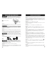
As you position the winch, make sure that the rope winds in the
proper rotation on the drum. Your winch is intended to operate
in one direction only. Failure to operate the winch in the proper direction can cause the
winch brake ( if equipped ) to operate improperly, and/or cause the winch to fail.
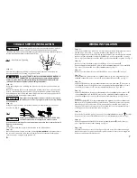
Step ( 2 )
Position the winch over the holes in the mounting kit or structural support.
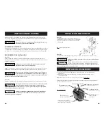
Fig. 2
- Winch mounting
Step ( 4 )
Secure roller fairlead or hawse
( Fig. 2 )
to mounting plate or structural support using
hardware supplied.
!
WARNING
!
Be sure that both the mounting plate and winch hardware have
been properly tightened.
CAUTION
!
No part of the vehicle ( skid plates, wiring, auxiliary lights, tires,
etc. ) should impede the operation of your Superwinch. When
mounting, check all vehicle and winch parts for free operation. Be sure that the winch
mounting location does not significantly reduce ground clearance.
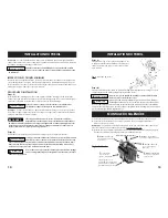
SOLENOID MOUNTING
1.
The solenoid disconnects your winch from the battery when the vehicle is
turned off.
2.
The solenoid should be mounted close to the battery and in a location that is
clean and dry as possible.
Note:
The solenoid should not be mounted in an orientation in which the contact
posts are in a downward position.
3.
Ensure the solenoid location selected provides sufficient clearance from all
metal structures, such as frame tubes.
CAUTION
!
Do not weld or machine any part of the winch. Machining or
welding may weaken the structural integrity of the winch and will
void your warranty.
Fig. 3 - Solenoid
4
5
Step ( 3 )
Secure winch ( Fig. 2 ) to mounting kit or structural
support using bolts, lock washers and square
nuts supplied with winch.
D.
terminal,
BLACK wires
,
to
Battery Negative (-) Terminal
A.
+ terminal
,
YELLOW wire
#1 to Motor positive “+”
B.-
terminal
,
BLUE wire
#2, to Motor negative “-”
C
. terminal
,
RED wire
to circuit breaker
unmarked
side.
Center spade connector
E.
,
connects the small black jumper
wire, only, (assembled as shown)
F.
outer left spade connector,
BLACK wires
G.
outer right spade
connector, GREEN wires
( Top of Solenoid )


