V 01-2017
www.superwind.com
55
Side
Mounting
Table No. 1.3.1
mm
inches
A
FRONT VIEW= length & width
48
1.88”
B
REAR VIEW= length & width
42
1.65”
C
Panel Maximum Fitting Space
22
0.86”
D1
Screw fitting hole1 OD
4.1
1.61”
D2
OD Switch axle
20
0.78”
F
Screws fitting holes distance OC
36
1.41”
L Inside
cabinet
55 2.16”
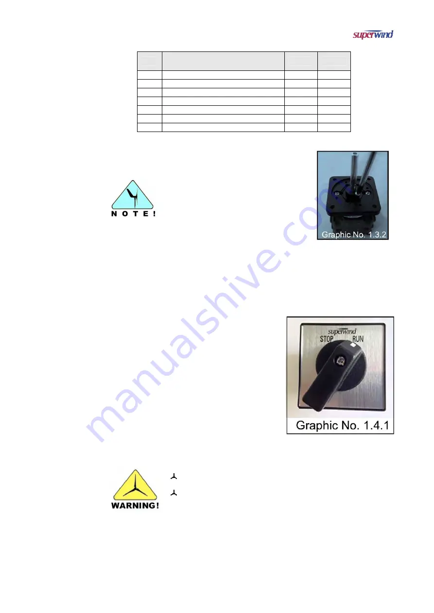
For very thin panels, it might be necessary
to cut off the screw’s head afterwards for
proper mounting. (Graphic No. 1.3.2)
1.4 Electrical
Connection
The stop switch has two positions:
a)
RUN
The positive wire from the generator
is
connected to the battery.
The negative wire from the
generator
is connected to the battery.
b)
STOP
The positive and the negative wires
from
the wind generator are short-
circuited
(generator short-circuit brakes the
rotor).
The positive and the negative lines
from
the battery are both open and
disconnected from the wind
generator.
Any electrical work may be accomplished only by authorize and
skilled persons!
During any connection work, the related electrical circuit must be
disconnected from the battery terminals!
Summary of Contents for 350 12V
Page 1: ...www superwind com Superwind 350 12V 24V Manual North Central and South America regions 01 2017...
Page 2: ...V 01 2017 www superwind com 1 Page intentionally left blank...
Page 52: ...V 01 2017 www superwind com 51 ATTACHMENT A Stop Switch Mounting Guidelines...
Page 53: ...V 01 2017 www superwind com 52 STOP SWITCH Mounting Guidelines Manual 01 2017...
Page 60: ...V 01 2017 www superwind com 59 ATTACHMENT B Superwind Charge Regulator 12V Marine...
Page 61: ...V 01 2017 www superwind com 60 Charge Regulator 12V Marine Instructions Manual 01 2017...
Page 70: ...V 01 2017 www superwind com 69 ATTACHMENT C Superwind Charge Regulator 24V Marine...
Page 71: ...V 01 2017 www superwind com 70 Charge Regulator 24V Marine Instructions Manual...


