Control Location
-17-
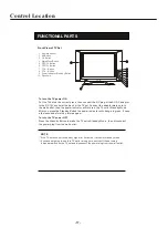
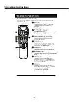
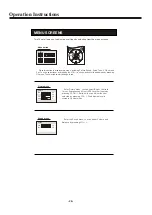
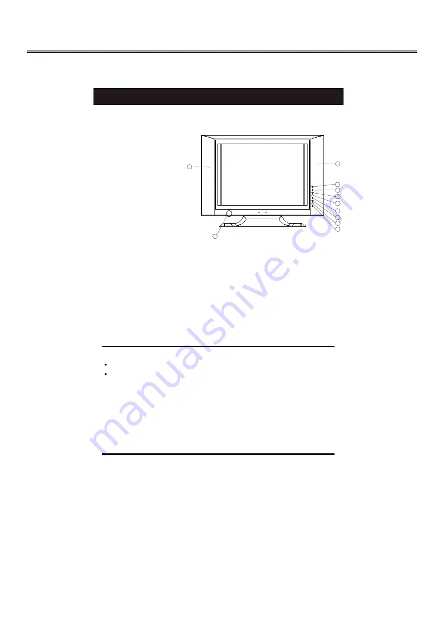
FUNCTIONAL PARTS
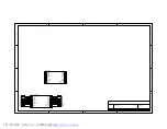
Front View of TV Set
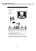
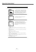
To turn the TV power OFF
Press the Standby Button to make the TV set in Standby Mode., then disconnect
the power plug from the wall outlet.
To turn the TV power ON
Put the TV set on the correct place, then connect the DC plug of the AC-DC adaptor
to the DC 12V socket at the back or the TV set. Connect the adaptor main cord to
the wall outlet, then the power indicator will turn red, the TV set at Standby Mode.
After you press the Standby Button the power indicator will change to green. It need
a few second before the picture appear.
If you are not going to use this TV set for a long time, switch off the set using
the power switch on the TV set and disconnect the power plug from the wall outlet.
NOTE
I
f the TV set does not receive any signal for 5 minutes, it will enter standby mode.
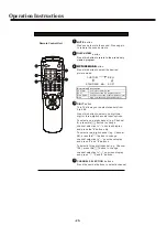
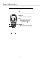
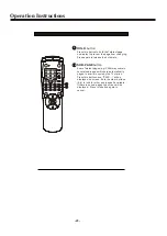
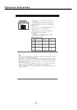
1. Remote Sensor
2. AV Button
3. OK Button
4. Main Menu Button
5. PROG.+Button
6. PROG.- Button
7. VOL.+Button
8. VOL.- Button
9. Power Indicator/Stand by Button
10. Speakers
10
10
10
10
1
1
2
2
3
3
4
4
5
5
6
6
7
7
8
8
9
9
Summary of Contents for 8T83
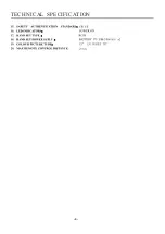
Page 3: ...TECHNICAL SPECIFICATION 3 Frequency L L CUSTOM SOFT STANDARD RICH LATIN GREEK...
Page 4: ...TECHNICAL SPECIFICATION 4...
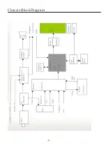
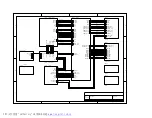
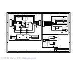
Page 5: ...Chassis Block Diagram 5...
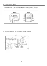
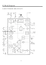
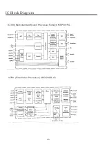
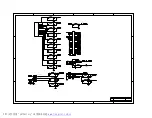
Page 7: ...IC2 MULTI STANDARD VIDEO IF TDA4470 IC602 POWER STR G6653 IC Block Diagram 7...
Page 10: ......
Page 11: ......
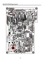
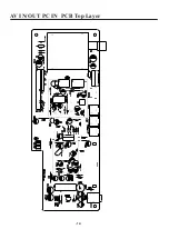
Page 12: ...AV IN OUT PC IN PCB Top Layer 12...
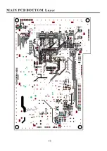
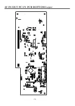
Page 13: ...13 AV IN OUT PC IN PCB BOTTOM Layer...
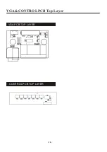
Page 14: ...14 VGA CONTROL PCB Top Layer VGA PCB TOP LAYER CONTROL PCB TOP LAYER...
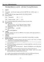
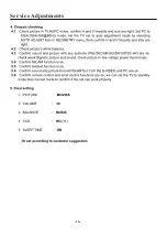
Page 15: ...Service Adjustments 15...
Page 16: ...Service Adjustments 16...