background image

Open


Beam


Protection 
kit


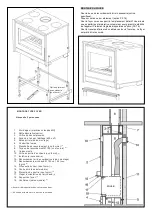
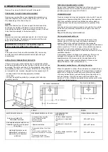
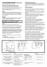
FIREPLACE CLADDING


Any personalised cladding around the fireplace must: 

Be of M0 material (non-combustible) 
Provide a free section of at least 600 cm² at the bottom 
to allow free circulation of air. 

5. USE 


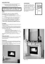
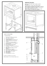
HOOD


We recommend the use of M0 class materials (non-
combustible)  
as well as the use of insulation. The design of a 
customised hood should: 
- allow free access to the interior or include an inspection 
door, 
- be independent of the hearth, which must not be used 
to support the hood. The appliance must be able to 
expand freely. 
- for appliances with a side-door opening, the brick strip or the 
hood have to be placed at least 1 cm beyond the front of the 
fireplace to allow air to circulate. 
 

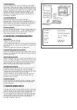
THE HOOD MUST INCLUDE THE FOLLOWING 
COMPONENTS 


False ceiling


The hood must have a false ceiling fixed at least 30 cm below 
the ceiling  
of the room. 

- This false ceiling channels the hot air outward, prevents it from 
remaining in the upper part of the hood and protects the ceiling 
in the room. Make the false ceiling using materials M0 class 
materials (non-combustible) and then insulate it. 

- The manufactured casing must: 

- have effective ventilation openings, 
communicating with the outside of the hood. 

- be airtight with respect to the lower part of the hood 
to stop   
hot air seeping upwards. 

Insulate the face of the box against the wall, the pipe and 
the ceiling.  


Hot air diffusers


One  or  more  distribution  vents  with  a  non-closable  free 
section  of  600  cm²  must  included  in  the  upper  part  of  the 
hood, flush with the false ceiling. 


Inspection door


The pipes that are connected to the flue must be visible along 
their entire length, either directly or via an inspection door or grille 
installed in the hood. 
The connection pipes must be accessible (in France; NF-DTU 
24.1) for cleaning purposes.  


FUEL


Wood


This high-performance appliance requires good quality fuel. 
Only burn air-dried logs (2 to 3 years, stored in a sheltered and 
well-ventilated place) with a maximum humidity of 15 to 20%. 
Preferably hardwoods (birch, hornbeam, beech, etc.). 
Avoid softwoods (lime, chestnut, willow, poplar). 
It is strictly forbidden to permanently use resinous wood (pine, 
fir...) as well as the use of waste from processed wood (railway 
sleepers, woodworking waste, etc.) and household scraps 
(vegetables or plastics). 
Never use small pieces of wood, boxes, woodchips or vine 
shoots that could lead to sudden overheating. 


DRAUGHT


The hot draught in the chimney flue must never be greater than 
20 Pa. Ask your dealer to measure the draught during the 
installation of the flue. If the combustion air is not connected, any 
use of controlled mechanical ventilation (CMV) may influence the 
draught, even reversing it. For this reason, the extractor must be 
running during measurement of the draught. 


CONTROLS


Orders


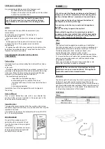
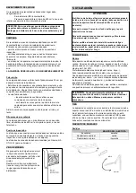
WOODEN BEAM


No part of the wooden beam (if it 
exists) should be subjected to heat 
from the inlet, pipe or rising air (glass 
convection). 
Assemble using insulation (rock wool) 
and a beam protection kit (optional) 
available from your dealer.   


Close


CAUTION: 

The use of coal or its derivatives is strictly 

prohibited, even on an occasional basis. This appliance 
must not be used to burn domestic waste.


CAUTION. In order to allow the hearth to expand freely, 
none of its parts must be in contact with the cladding.


Keep a distance of 5 mm between the cladding and the 
fireplace. 


CAUTION:


- If a niche under the fireplace is being used as firewood 
storage, never block it completely (a front opening with a 
section of at least 600 cm² must remain free at all times).


Leave a space of at least 5 cm between the bottom of 
the fireplace and the top of the logs.


To avoid any risk of burns, do not touch the appliance 
and use  
the cool hand key to operate the controls.


Heat emitted through the vitro ceramic glass makes it 
necessary to keep any material that could be damaged by 
heat (furniture, wallpaper, carpentry, etc.) away from the 
hearth.  A 2 m clearance will avoid any risk.


*


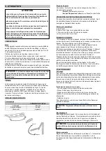
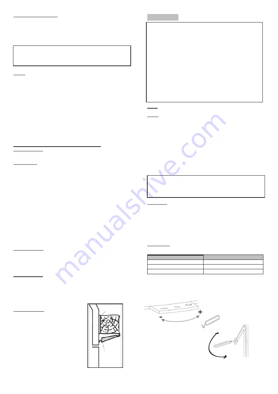
STOVE CONTROLS


Light 

right 

Nominal output 

centre 

Minimum output 

left 


Summary of Contents for NEO 76 16/9 GT

Page 1: ...CT RISTIQUES TECHNIQUES 2 PRINCIPE DE RACCORDEMENT 3 INSTALLATION EN INSERT 4 INSTALLATION EN FOYER 5 UTILISATION 6 ENTRETIEN 7 SERVICE APR S VENTE Illustrations non contractuelles NOTICE D INSTALLATI...

Page 2: ...tible solide Disponibles l AFNOR IMPORTANT Vous venez d acqu rir un appareil de notre gamme Nous vous f licitons de votre choix Cet appareil a t tudi avec soin Pour en tirer tous les avantages que vou...

Page 3: ...lation de mati res pouvant tre d t rior es ou alt r es par la chaleur mobilier papier peint boiseries proximit imm diate de l appareil La mise en place d un r cup rateur de chaleur de quelque type que...

Page 4: ...e raccord e 150 un tubage d vacuation des fum es cf DTU 24 1 FOYER La buse de sortie de fum e doit tre raccord e 150 un conduit d vacuation des fum es cf DTU 24 1 L air chaud sort par la fa ade de l a...

Page 5: ...air frais est indispensable une bonne combustiondu foyer Le fonction nement est optimal avec une consommation d air frais de 40 m3 h environ Un syst me de ventilation type VMC une aspiration centralis...

Page 6: ...du d flecteur 3 Extraire le d flecteur du foyer 4 Remonter le d flecteur dans le foyer 5 Verrouiller le d flecteur dans le foyer sur les pattes de fixation RACCORDEMENT AU CONDUIT DE FUM ES D poser l...

Page 7: ...cte non raccord e dans la pi ce est possible respecter les pr conisations suivantes Air de combustion non raccord Si l air de combustion n est pas raccord directement l ext rieur par un conduit une am...

Page 8: ...class s MO 2 Hotte d corative option 3 Orifice de d compression 4 Acc s de l air par l abillage 600 cm2 5 But e arri re selon montage 6 Conduit de fum e 7 Manchette de raccordement non fournie 1 8 Tu...

Page 9: ...ur le dessus du foyer Fixer l autre extr mit de ces gaines sur une grille obturable simple ou double pour r gler le d bit d air chaud en fonction de l installation Ne jamais obturer simultan ment tout...

Page 10: ...lass s M0 incombustibles puis l isoler Le caisson fabriqu doit comporter des ouvertures de ventilation efficaces en communication vers l ext rieur de la hotte tre tanche par rapport la partie inf rieu...

Page 11: ...e simultan e de 2 b ches au moins vers le fond du foyer Il est pr f rable de charger en plusieurs fois plut t que de mani re excessive En cas de temp rature ext rieure tr s basse un bouchon thermique...

Page 12: ...du cadre de la porte ne pas utiliser d eau de solvant ou de produit abrasif m me l g rement mais uniquement un chiffon doux et sec NETTOYAGE DE LA VITRE Nettoyer le vitrage froid avec un chiffon humid...

Page 13: ...LE 3 INSERT INSTALLATION 4 HEARTH INSTALLATION 5 USE 6 MAINTENANCE 7 AFTER SALES SERVICE HEARTH INSERT ENGLISH N O 76 G N O 76 16 9 GT NEO 76 16 9 G NEO 76 G Non binding illustrations INSTALLATION INS...

Page 14: ...Option PS 76 IMPORTANT You have just purchased an appliance from our range We would like to congratulate you on your choice This appliance has been carefully designed In order to get the very best ou...

Page 15: ...n to Place materials that could be damaged or affected by the heat furniture wallpaper woodwork etc close to the appliance Install any type of heat recovery system not recommended by the manufacturer...

Page 16: ...llar has to be connected 150 to a flue see DTU 24 1 HEARTH The flue collar has to be connected 150 to a flue see DTU 24 1 The hot air comes out through the front of the appliance Optionally hot air ca...

Page 17: ...esh air is essential for good combustion in the hearth Fresh air consumption of approximately 40m3 h provides optimal operation CMV type ventilation systems centralised vacuum systems or kitchen extra...

Page 18: ...ing catches in towards the hearth 2 Lower the rear part of the baffle 3 Take the baffle out of the hearth 4 Fit the baffle back into the hearth 5 Use the holding catches to lock the baffle to the hear...

Page 19: ...s Unconnected combustion air Should the combustion air not be connected directly to the outside via a duct then the room must have a permanent supply of fresh air but without it disturbing the occupan...

Page 20: ...ls 2 Decorative hood optional 3 Decompression hole 4 Air access through the casing 600 cm2 5 Rear stop depending on assembly 6 Flue pipe 7 Connection sleeve not supplied 1 8 Connection pipes 150 not s...

Page 21: ...AIR When delivered the hot air damper is open Hot air comes out the front of the fireplace towards the room DISTRIBUTION OF HOT AIR Connect the hot air distribution nozzles optional see specific docum...

Page 22: ...to 3 years stored in a sheltered and well ventilated place with a maximum humidity of 15 to 20 Preferably hardwoods birch hornbeam beech etc Avoid softwoods lime chestnut willow poplar It is strictly...

Page 23: ...til there is a good bed of embers and the flames have gone out It is best to load in the wood several times rather than all at once Too much fuel will cause the appliance to overheat and damage it MIN...

Page 24: ...L Combustion air collar D Hearth plate E Grating B Fa ade C Door F Hearth base A Ash box G Control knob H J K Fixing plates...

Page 25: ...1 CARACTER STICAS T CNICAS 2 PRINCIPIO DE CONEXI N 3 INSTALACI N INSERT 4 INSTALACI N HOGAR 5 UTILIZACI N 6 MANTENIMIENTO 7 SERVICIO POSTVENTA Ilustraciones no contractuales MANUAL DE INSTALACI N Y FU...

Page 26: ...rata de los conductos de humo DTU 24 2 que trata de las chimeneas equipadas con una estufa cerrada NF EN13229 que trata de las estufas de combustible s lido Disponibles en AFNOR IMPORTANTE Acaba de ad...

Page 27: ...puedan verse da ados o alterados por el calor muebles papel pintado carpinter a etc en las inmediaciones del aparato La instalaci n de cualquier tipo de recuperador de calor no recomendado por el fab...

Page 28: ...i n de aire caliente La boquilla de salida de humos debe estar conectada 150 a un tubo de evacuaci n de humos ver DTU 24 1 HOGAR La boquilla de salida de humos debe estar conectada 150 a un conducto d...

Page 29: ...cionamiento es ptimo con un consumo de aire fresco de unos 40 m3 h aproximadamente Un sistema de ventilaci n tipo VMC una aspiraci n centralizada o una campana de cocina pueden interferir con el funci...

Page 30: ...hogar 2 Levante la parte trasera del deflector 3 Saque el deflector del hogar 4 Vuelva colocar el deflector en el hogar 5 Bloquee el deflector en el hogar con las patas de fijaci n CONEXI N AL CONDUC...

Page 31: ...ecomendaciones siguientes Aire de combusti n no conectado Si el aire de combusti n no est conectado directamente al exterior a trav s de un conducto se debe proporcionar un suministro permanente de ai...

Page 32: ...M0 2 Campana decorativa opcional 3 Puerto de descompresi n 4 Acceso del aire por el revestimiento 600 cm2 5 Tope posterior seg n montaje 6 Conducto de humos 7 Manguito de conexi n no suministrado 1 8...

Page 33: ...trados a las boquillas que se instalar n en la parte superior del hogar Fije el otro extremo a una rejilla sellable simple o doble para ajustar el flujo de aire caliente seg n la instalaci n Nunca cie...

Page 34: ...o del aire ascendente convecci n del cristal Realice el montaje con aislamiento lana de roca y el kit de protecci n de la viga opcional disponible en su distribuidor 5 UTILIZACI N COMBUSTIBLES Madera...

Page 35: ...anzar la potencia nominal Coloque la carga de madera hacia el fondo del hogar para evitar la ca da de brasas En la medida de lo posible no recargue el hogar hasta que haya un buen lecho de brasas y la...

Page 36: ...F Inferior del hogar G Perilla de control H J K Elementos de fijaci n L Boquilla de aire de combusti n A Cenicero B Frontal C Puerta D Placas de la chimenea E Rejillas...

Page 37: ...NEX O 3 INSTALA O EMBUTIDA 4 INSTALA O DE LAREIRA 5 UTILIZA O 6 MANUTEN O 7 SERVI O DE P S VENDA LAREIRA EMBUTIDA PORTUGU S N O 76 G N O 76 16 9 GT NEO 76 16 9 G NEO 76 G Ilustra es n o contratuais MA...

Page 38: ...Hz Op o montagem da s rie GT Bocais de distribui o de ar quente 125 ou 150 apenas para instala o no domic lio Op o Kit de prote o de vigas Op o P s Op o PS 76 IMPORTANTE Acaba de adquirir uma salamand...

Page 39: ...u alterados pelo calor m veis papel pintado carpintaria etc nas imedia es do aparelho A instala o de qualquer tipo de recuperador de calor n o recomendado pelo fabricante A utiliza o de qualquer combu...

Page 40: ...ado 150 a um tubo de exaust o de fumos ver DTU 24 1 LAREIRA O bocal de sa da de fumos deve estar conectado 150 a um tubo de exaust o de fumos ver DTU 24 1 o ar quente sai pela parde de tr s do aparelh...

Page 41: ...rdo com o O ar fresco essencial para uma boa combust o da lareira O funcionamento timizado com um consumo de ar fresco de 40 m3 h aproximadamente Um sistema de ventila o tipo VMC uma aspira o centrali...

Page 42: ...dois p s de fixa o na dire o do interior da lareira 2 Levante a parte traseira do defletor 3 Retire o defletor de dentro da lareira 4 Volte a colocar o defletor na lareira 5 Bloqueie o deflector na l...

Page 43: ...a na divis o Siga as seguintes recomenda es Ar de combust o n o conectado Se o ar de combust o n o est diretamente conectado ao exterior atrav s de uma conduta deve assegurar se um fornecimento perman...

Page 44: ...M0 2 Extrator decorativo opcional 3 Porto de descompress o 4 Acesso do ar atrav s do revestimento 600 cm2 5 Cobertura posterior de acordo com a montagem 6 Conduta de fumos 7 Tubo de conex o n o fornec...

Page 45: ...QUENTE No momento da entrega a v lvula de orienta o do ar quente est aberta O ar quente sai pela parte da frente da lareira para a divis o DISTRIBUI O DO AR QUENTE Conecte os bocais de distribui o de...

Page 46: ...o ar 2 a 3 anos armazenada num local abrigado e ventilado com um grau de humidade m xima de 15 a 20 Preferencialmente madeiras duras b tula carpa faia etc Evite as madeiras macias tilo castanheiro sal...

Page 47: ...rminada por quantidade de combust vel O bom funcionamento do aparelho depende do fornecimento adequado de ar para o fundo do aparelho para evitar a queda de brasas Fa a a recarga do aparelho quando as...

Page 48: ...L Bocal do ar de combust o D Placas da lareira E Grelhas B Painel frontal C Porta F Base da lareira A Cinzeiro G Unidade de controlo H J K Elementos de fixa o...

Page 49: ...INSTALLAZIONE INSERT 4 INSTALLAZIONE FOCOLARE 5 UTILIZZO 6 MANUTENZIONE 7 SERVIZIO DI POSTVENDITA FOCOLARE INSERT ITALIANO N O 76 G N O 76 16 9 GT NEO 76 16 9 G NEO 76 G Illustrazioni non contrattual...

Page 50: ...rie GT Bocchette di distribuzione dell aria calda 125 o 150 solo per installazione in focolare Opzione Kit di protezione della trave Opzione Piedini Opzione PS 76 IMPORTANTE Ha appena acquistato un ap...

Page 51: ...ere danneggiati o alterati dal calore mobili carta da parati carpenteria ecc nei pressi dell apparecchio L installazione di qualsiasi tipo di recuperatore di calore non raccomandato dal fabbricante L...

Page 52: ...dere DTU 24 1 FOCOLARE La bocchetta di uscita dei fumi deve essere collegata 150 a un condotto di dispersione dei fumi vedere DTU 24 1 L aria calda esce dalla parte frontale dell apparecchio Opzionalm...

Page 53: ...a quanto L aria fresca essenziale per una buona combustione nel focolare Il funzionamento ottimale con un consumo di aria fresca di circa 40 m3 h Un sistema di ventilazione tipo VMC un aspirazione ce...

Page 54: ...issaggio verso l interno del focolare 2 Alzare la parte posteriore del deflettore 3 Estrarre il deflettore dal focolare 4 Riposizionare il deflettore nel focolare 5 Bloccare il deflettore nel focolare...

Page 55: ...re le seguenti raccomandazioni Aria di combustione non collegata Se l aria di combustione non collegata direttamente all esterno tramite un condotto si deve fornire un alimentazione permanente di aria...

Page 56: ...o dell aria attraverso il rivestimento 600 cm2 5 Finecorsa posteriore in base al montaggio 6 Condotto dei fumi 7 Manicotto di connessione non in dotazione 1 8 Tubi di collegamento 150 non in dotazione...

Page 57: ...ZIONE NATURALE DELL ARIA CALDA Al momento della consegna la valvola di orientazione dell aria calda aperta L aria calda esce dalla parte frontale del focolare verso la stanza DISTRIBUZIONE DELL ARIA C...

Page 58: ...e legna in tronchi asciugata all aria da 2 a 3 anni stoccata in un luogo protetto e ventilato con un umidit massima compresa tra il 15 e il 20 Sono preferibili legnami duri betulla carpino faggio Evit...

Page 59: ...e l apparecchio quando si sia formato un buon letto di braci e le fiamme siano sparite preferibile caricare varie volte che farlo eccedendo le quantit Una carica eccessiva far surriscaldare l apparecc...

Page 60: ...L Bocchetta dell aria di combustione D Piastre del camino E Griglie B Frontale C Porta F Parte inferiore del focolare A Portacenere G Manopola di controllo H J K Elementi di fissaggio...

Page 61: ...CHLUSSES 3 MONTAGE KAMINEINSATZ 4 MONTAGE KAMINOFEN 5 VERWENDUNG 6 INSTANDHALTUNG 7 KUNDENDIENST KAMINOFENEINSATZ DEUTSCH N O 76 G N O 76 16 9 GT NEO 76 16 9 G NEO 76 G Nicht vertragliche Bilder INSTA...

Page 62: ...ion Balkenschutz Kit Option F e Option PS 76 WICHTIG Sie haben soeben einen Kaminofen aus unserem Sortiment erworben Gl ckwunsch zu Ihrer Wahl Dieser Kaminofen wurde mit gro er Sorgfalt entworfen Um i...

Page 63: ...on der Hitze besch digt oder ver ndert werden k nnten M bel Tapeten Holzgegenst nde etc in der N he des Ofens Die Installation jeglicher Art von W rmer ckgewinnungsger ten die nicht vom Hersteller emp...

Page 64: ...Rauchabzugsstutzen muss an ein Abgasrohr angeschlossen werden 150 siehe DTU 24 1 KAMINOFEN Der Rauchabzugsstutzen muss an ein Abgasrohr angeschlossen werden 150 siehe DTU 24 1 Die hei e Luft tritt an...

Page 65: ...steins Stabilit t Dichtheit Kompatibilit t der Materialien Querschnitt usw in Frankreich NF DTU 24 1 Lassen Sie den Schornstein mechanisch reinigen und ggf entfernen Lassen Sie einen fachkundigen Rauc...

Page 66: ...von 1 2 dm haben Der Querschnitt in cm des L ftungsgitters der L ftungskammer muss mindestens das 5 fache der Fl che in m der L ftungskammer betragen Die permanente Au enluftzufuhr ist nicht erforder...

Page 67: ...Kaminofens 2 Heben Sie die R ckseite des Deflektors an 3 Entnehmen Sie den Deflektor aud em Kaminofen 4 Setzen Sie den Deflektor wieder in den Kaminofen ein 5 Verriegeln Sie den Deflektor mit den Arr...

Page 68: ...zufuhr zul ssig Beachten Sie die folgenden Empfehlungen Verbrennungsluft nicht angeschlossen Wenn die Verbrennungsluft nicht direkt ber ein Rohr mit dem Au enbereich verbunden ist muss eine Frischluft...

Page 69: ...optional 3 Dekompressionsanschluss 4 Luftzugang durch die Ummantelung 600 cm2 5 Hinterer Anschlag je nach Einbau 6 Rauchableitungsrohr 7 Anschlussmuffe nicht im Lieferumfang enthalten 1 8 Anschlussro...

Page 70: ...hdeflektor NAT RLICHE VERTEILUNG VON HEISSLUFT Im Auslieferungszustand ist das Hei luftleitventil ge ffnet Warme Luft tritt an der Vorderseite des Ofens in den Raum aus VERTEILUNG VON HEISSLUFT Schlie...

Page 71: ...leistungsofen erfordert einen Qualit tsbrennstoff Nur an der Luft getrocknetes Brennholz 2 bis 3 Jahre an einem gesch tzten und bel fteten Ort gelagert in St mmen mit einer maximalen Feuchtigkeit von...

Page 72: ...Ofen um herabfallende Glut zu vermeiden Beschicken Sie den Ofen nach M glichkeit erst wieder wenn ein gutes Glutbett vorhanden ist und die Flammen verschwunden sind Es ist besser den Ofen mehrmals zu...

Page 73: ...hen sind mindestens 2 Holzscheite ca 2 9 kg h erforderlich Geben Sie die Holzladung G Bedienknopf H J K Befestigungselemente F Unterer Teil des Ofens D Schornsteinbleche E Gitter L Verbrennungsluftd s...

Page 74: ......

Page 75: ......

Page 76: ......

Page 77: ......

Reviews: