2. INSTALLATION
DEFINITION
Wood burning stove designed for installation close to a wall , and
which can be moved with no need for additional work. The
connection to the flue pipe is made through stainless steel or
vitreous enamel pipes conforming to standard NFD 35-302. The
connection must be made to an individual flue pipe.
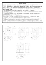
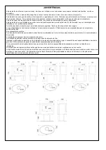
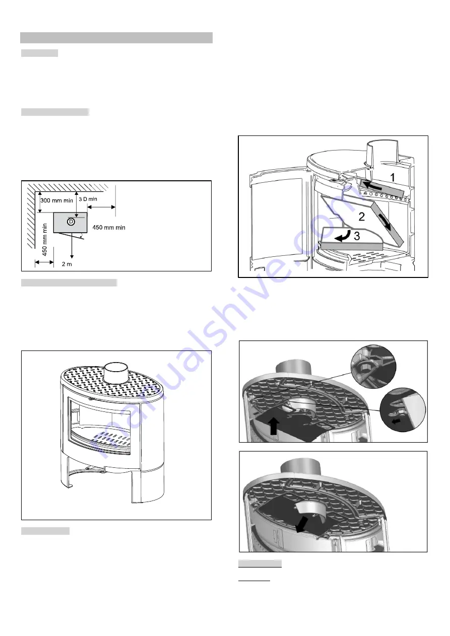
SAFETY CLEARANCE
Comply with the safety clearances indicated between the wall and
the sides or the back of the appliance.
If the wall is non-
combustible, then the safety clearance does not apply.
Regardless of the orientation of the stove, there must be a
clearance of 2 m between the glass and the wall or any flammable
material.
PREPARATION OF THE STOVE
Unpack the appliance: remove the screws securing it to the pallet.
Install the stove on a floor with sufficient load-bearing capacity. If
the floor cannot support the load, then measures should first be
taken (for example, the installation of a load distribution plate).
Position the stove in its definitive location and level it. For ease of
maintenance, it is recommended to lay tiles or some other type of
covering in the load-bearing area.
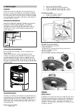
BAFFLE PLATE
The baffle plate comprises 2 vermiculate plates. It ensures
improved heat transfer and facilitates the recovery of the soot
during sweeping. The baffle plate is mounted when the appliance
is delivered. Before definitively installing the appliance, the baffle
plate should be mounted and dismounted a number of times in
order to become familiar with its operation.
Mounting the baffle plate
1.
Open the door
2.
Lift up the 2 halves of the baffle plate.
3.
Move them towards the rear of the stove.
4.
Tilt the right baffle plate half downwards and take it out.
5.
Tilt the left baffle plate half downwards and take it out.
Mounting the baffle plate
1.
Mount the left baffle plate half.
2.
Mount the right baffle plate half.
Left cross section. Left baffle plate half
Mounting the second baffle plate
1.Remove the vermiculite baffle plates.
2.
The procedure is as follows:
- Unscrew from the inside of the heating chamber the 2 fixing
screws of the deflector
- Remove the deflector
For reassembly, proceed in the reverse order
CONNECTION
AIR INLET
It will be necessary to get a fresh air intake positioned facing the
prevailing winds to permit correct combustion, particularly if the
house is heavily insulated and/or fitted with a controlled


