background image

  Installation 

14 

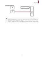
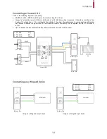
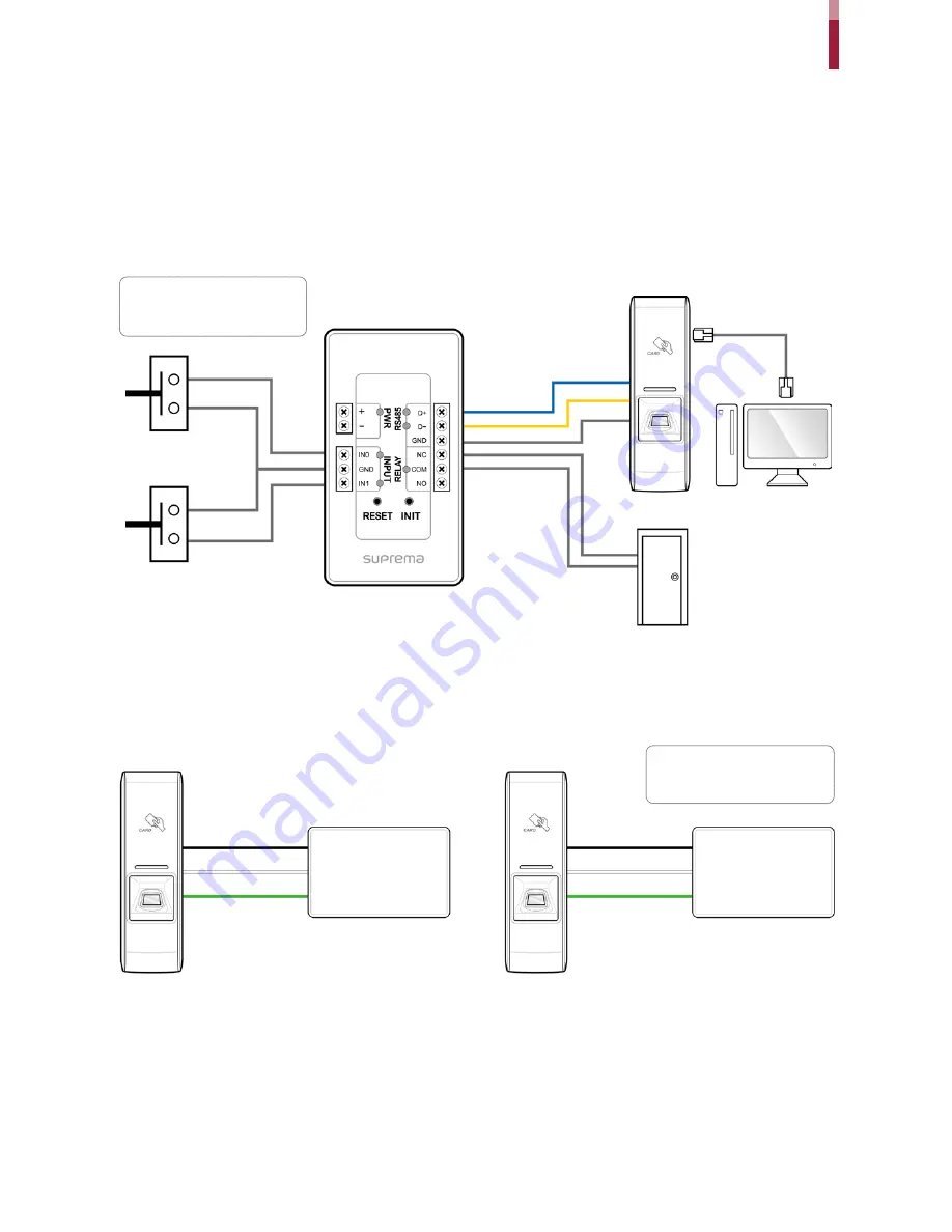
Connecting to Secure I/O 2 

Refer to the following figure for connecting. 


RS-485 should be AWG24, twisted pair, and maximum length is 1.2 km. 


Connect  a  termination  resistor  (120Ω)  to  both  ends  of  a  RS

-485 daisy chain connection. It should be installed at bot

h ends of the daisy chain. If it is installed in the middle of the chain, the performance in communicating will deterior

ate because it reduces the signal level. If the termination resistor of BioEntry Plus is required, set the #1 DIP switch 

to ON.  


Up to 32 devices can be connected via daisy chain (1 master device and 31 other devices). 


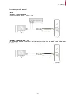
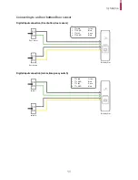
Connecting as a Wiegand device 


RFID reader 

1 -  WG D0 

Green 

2 -  WG D1 

White 

3 -  WG GND 

Black 


Controller 

BioEntry Plus 

BioEntry Plus 

Using as a Wiegand input device 

Using as a Wiegand output device 

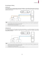
BioEntry Plus 

PC 

Door  Lock 

Secure I/O 2 

Input 0 

Door button 

Door sensor 

Input 1 

3 -  485 GND 

Gray 

4 -  485 TRXP 

Blue 

5 -  485 TRXN 

Yellow 


Summary of Contents for bioentry PLUS

Page 1: ...BioEntry Plus INSTALLATION GUIDE EN 101 00 BEP V2 12A Version 2 12 English...

Page 2: ...Network 10 TCP IP 10 Connecting to an Door button Door sensor 11 Digital input connection Door button Door sensor 11 Digital input connection Alarm Emergency switch 11 Connecting to a Relay 12 Fail Sa...

Page 3: ...c shock or injury If the product is damaged due to a user s unauthorized installation or dismantling of the product a service fee will be charged for repair Operating Instructions Be careful not to sp...

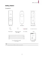
Page 4: ...nts NOTE Components may vary according to the installation environment BioEntry Plus Wall Bracket Diode Fixing Screw x 2 Bracket Fixing Screw Star Shaped 3 pin 4 pin 5 pin 7 pin cables 1 pc for each Q...

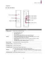
Page 5: ...ery 2 seconds Failure to reset Contact the manufacturer Yellow flashes every 2 seconds Waiting for an input Fingerprint reader Reads fingerprints placed on it for entering and exiting 5 pin cable conn...

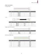
Page 6: ...ame Color RJ45 Pin number 1 ENET TXP Yellow 6 2 ENET TXN Green 3 3 ENET RXP Red 2 4 ENET RXN Black 1 Wiegand input output switchable Pin Name Color 1 WG D0 Green 2 WG D1 White 3 WG GND Black Digital i...

Page 7: ...rint Registering a finger is the most important procedure because this device uses the registered fingerprint to compare it with a fingerprint that the device tries to read Please ensure the following...

Page 8: ...lled onto a concrete wall make a hole with a drill and then insert a PVC anchor into the hole before screwing the mounting screw 2 Attach BioEntry Plus onto the mounted bracket 3 Assemble BioEntry Plu...

Page 9: ...by other devices the power adapter should provide a current more than the sum of the power consumption from this device 1 500 mA and other devices Use a separate power supply for Secure I O 2 electri...

Page 10: ...can be used to connect to a hub LAN connection connecting directly to a PC BioEntry Plus can be connected directly to a PC by using a normal straight type CAT 5 cable because it supports an automatic...

Page 11: ...r button Door sensor Digital input connection Alarm Emergency switch Switch 1 Switch 0 BioEntry Plus 1 TTL IN0 Yellow 2 TTL GND Black 3 TTL IN1 Green 4 TTL GND Black 4 3 2 1 Door sensor Door button Bi...

Page 12: ...r BioEntry Plus from the door lock device Fail Secure Lock To use fail secure lock connect N O terminal as shown below Normally there is no current flowing through the relay and the door is opened whe...

Page 13: ...ntry Plus PC Door button Door sensor Door Lock Input 0 Relay Input 1 1 TTL IN0 Yellow 2 TTL GND Black 3 TTL IN1 Green 4 TTL GND Black 5 RLY NC Orange 6 RLY COM Blue 2 1 5 6 4 3 BioEntry Plus Automatic...

Page 14: ...ting will deterior ate because it reduces the signal level If the termination resistor of BioEntry Plus is required set the 1 DIP switch to ON Up to 32 devices can be connected via daisy chain 1 maste...

Page 15: ...e device with default values TCP IP address DHCP address assignment If DHCP address assignment is failed 169 254 0 1 will be set Server mode Disabled RS 485 Default 115200 bps 4 Change the TCP IP addr...

Page 16: ...wo templates per finger Max Template 1 N 10 000 Two templates per finger Max Text Log 50 000 Interface TCP IP Yes RS 485 1ch Host or Slave Selectable Wiegand 1ch In or Out Selectable TTL Input 2 Input...

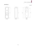
Page 17: ...Product Specifications 17 Dimensions Unit mm Front view Side view Bracket...

Page 18: ...if not installed and used in accordance with the instructions may cause harmful interference to radio communications However there is no guarantee that interference will not occur in a particular inst...

Page 19: ...ve employees subsidiaries branches partners and distributors of Suprema are exempt from liability even when it is claimed that there is a significant fault in the design or production process and also...

Page 20: ...nquiry sales supremainc com 2018 Suprema Inc Suprema and identifying product names and numbers herein are registered trade marks of Suprema Inc All non Suprema brands and product names are trademarks...

Reviews: