7
2.6.3.
System type
Select System Type Installed AC or HP
The type of system must be selected:
1. AC – Air Conditioner provides approximately 400 CFM
per ton for greater efficiency and humidity control with
the AC/HP CFM ADJUST set to the nominal (NOM)
tap. To achieve more or less than 400 CFM per ton,
move tap to (HI) or (LO) position respectively. Refer to
appropriate airflow tables for exact CFM setting.
2. HP-COMFORT – Heat Pump Comfort provides
approximately 350 CFM per ton for higher than normal
heating air delivery temperature.
3. HP-EFF – Heat Pump Efficiency provides same airflow
for heating and cooling modes to increase overall HP
efficiency; approximately 400 CFM per ton with the
AC/HP CFM ADJUST set to the nominal (NOM) tap.
The factory setting is AC (Refer to Figures 4 and 9).
2.6.4.
AC/HP CFM adjust
Select Medium, Low, or High Airflow
To provide airflow at rates described above, the AC/HP
ADJUST select is factory set to the nominal (NOM) tap. The
adjust selections HI/LO will regulate airflow supplied for all
operational modes.
HI provides 10% airflow over nominal unit size selected and LO
provides 10% airflow below nominal unit size selected.
Adjust selection options are provided to adjust airflow supplied
to meet individual installation needs for such thins as noise,
comfort, and humidity removal. (Refer to Figures 4 and 9)
2.6.5.
ON/OFF delay
Select desired time delay profile
NOTE:
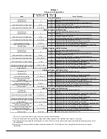
Delay selections are active in cooling and heat pump
heating modes only. Electric heating modes have a one (1)
minute OFF delay at 50% airflow and zero (0) ON delay
programmed into the ECM motor that cannot be overridden.
Four (4) motor operation delay profiles are provided to
customize and enhance system operation. (Refer to Figures 4
and 9)
Selection options are:
1. 0/90: No ON delay and 90 second OFF delay at 100%
airflow (factory setting).
2. 30/90: 30 second ON delay with no airflow and 90
second OFF delay at 100% airflow profile. Used when
it is desirable to allow system coils time to heat-
up/cool-down in conjunction with the airflow.
3. 0/0: No delay option. Used for servicing unit or when a
thermostat is utilized to perform delay functions.
4. ENH: enhanced selection provides a 30 second ON
delay with no airflow followed by 150 seconds at 70%
airflow, and no OFF delay for added comfort. This
profile will minimize cold blow in heat pump operation
and could enhance system efficiency.
2.6.6.
Continuous fan
Select desired fan speed when thermostat is set on
continuous fan. (Refer to figure 4 and 9)
NOTE:
If installed with a two-stage outdoor unit, do not select HI
speed continuous fan. If HI is selected, low stage compression
will also run HI fan speed possibly resulting in insufficient
dehumidification.
1. LO speed – factory setting, 50% cooling mode airflow.
2. MED speed – move connector to MED, 80% cooling
mode airflow.
3. HI speed – move connector to HI, 100% cooling mode
airflow.
2.6.7.
Low-voltage circuit
Fusing and Reference
The low-voltage circuit is fused by a board-mounted 5-amp
automotive fuse placed in series with the transformer SEC2 and
the R circuit. The C circuit of the transformer is referenced to
chassis ground through a printed circuit run at SEC1 connected
to metal standoff marked with ground symbol.
2.6.8.
Basic furnace configuration
The following basic configuration of the furnace will provide ARI
rated performance of an air conditioner:
1. HEAT KW/CFM – Select the heater range for the size
electric heater installed.
2. AC/HP SIZE – Select system size installed.
3. SYSTEM TYPE – Select system type AC
4. AC/HP CFM ADJUST – Select NOM.
5. ON/OFF DELAY – Select 0/90 profile.
6. CONTINUOUS FAN – Select desired fan speed when
thermostat is set to continuous fan.
The following basic configuration of the furnace will provide ARI
rated performance of a heat pump:
1. HEAT KW/CFM – Select the heater range for the size
electric heater installed.
2. AC/HP SIZE – Select system size installed.
3. SYSTEM TYPE – Select system type HP-EFF
4. AC/HP CFM ADJUST – Select NOM.
5. ON/OFF DELAY – Select 0/90 profile.
6. CONTINUOUS FAN – Select desired fan speed when
thermostat is set to continuous fan.
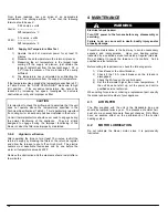
2.7 INSTALLATION
OF
ACCESSORIES
WARNING
Electrical shock hazard.
Turn OFF electrical power at the fuse box or service panel
before making any electrical connections and ensure a
proper ground connection is made before connecting line
voltage.
Failure to do so can result in death or bodily injury.
Summary of Contents for FEM15-E230V1M-A
Page 12: ...12 FIGURE 9 Diagramme électrique ...
Page 17: ...17 COMPOSANTES ET PIÈCES DE REMPLACEMENT ...
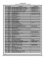
Page 18: ...18 LISTE DE PIÈCES Vue explosée B50081 Rev B ...
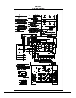
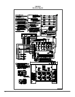
Page 31: ...12 FIGURE 9 Electrical Diagram ...
Page 36: ...17 COMPONENTS AND REPLACEMENT PARTS ...

