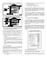
9
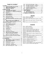
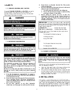
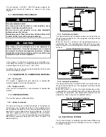
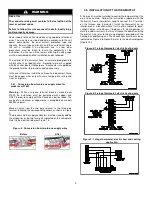
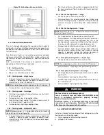
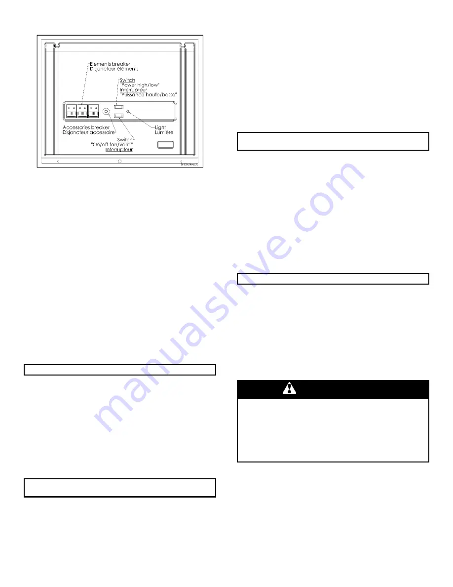
Figure 14 : Advantage furnace controls
3.3- OPERATING SEQUENCE
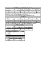
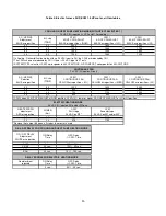
This unit is designed to provide the required airflow in order to
match with any of four (4) different electronic heat capacity, air
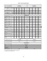
conditioner or heat pump outdoor unit sizes (see Tables 3 and 4
for CFM values).
Also, the blower motor is a true variable speed motor designed
to deliver constant CFM. Constant CFM is valid for systems with
total external static pressure between 0.1 and 0.8 inches water
column.
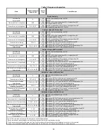
Refer also to Table 1 for sequence of operation summary,
depending on thermostat inputs and types.
3.3.1- Continuous fan
•
Thermostat closes circuit R to G.
•
Blower runs at continuous fan airflow.
3.3.2- Cooling mode – single stage
•
If indoor temperature is above temperature set point and
humidity is below humidity set point, thermostat closes
circuits R to G, R to Y/Y2 and R to O.
NOTE:
For single stage systems, do not use the Y1 terminal.
•
Furnace delivers single stage cooling airflow.
3.3.3- Cooling mode – two stage
•
First stage (low) cooling: Thermostat closes circuits R to G,
R to O, and R to Y1.
•
Furnace delivers low stage cooling airflow.
•
Second stage (high) cooling: Thermostat closes circuits R
to G, R to O, R to Y1 and R to Y/Y2.
•
Furnace delivers high stage cooling airflow.
3.3.4- Cooling mode – dehumidification
NOTE:
Remove jumper « J1 » on board to activate this function.
(Refer to Figure 10 and Figure 16)
•
If indoor temperature is above temperature set point and
humidity is above humidity set point, thermostat closes
circuits R to G, R to Y/Y2 and R to O and humidistat opens
circuit R to DH.
•
The furnace delivers airflow which is approximately 80% of
the nominal cooling airflow to increase the latent capacity of
the system.
3.3.5- Electric heating mode – 1 stage
•
Thermostat closes circuit R to W1 or W2.
•
Furnace delivers the selected electric heat airflow and
maximum heating capacity is powered starting the heating
elements in sequence with a delay of 8 seconds between
each.
3.3.6- Electric heating mode – 2 stage
NOTE:
Remove jumper « J2 » on board to activate this function.
(Refer to Figures 9 and 15)
•
First stage heating: thermostat closes circuit R to W1.
•
Furnace delivers low stage heating airflow (50% of nominal
electric heating airflow) and approximately half of the
heating capacity is powered starting the heating elements
in sequence with a delay of 8 seconds between each.
•
Second stage heating:thermostat closes circuit R to W2.
•
Furnace delivers high stage heating airflow (100% of
nominal electric heating airflow) and maximum heating
capacity is powered starting the heating elements in
sequence with a delay of 8 seconds between each.
3.3.7- Heat pump heating mode – single stage
•
Thermostat closes circuits R to G and R to Y/Y2.
NOTE:
For single stage systems, do not use the Y1 terminal.
•
Furnace delivers single stage heat pump heating airflow.
3.3.8- Heat pump heating mode – two stage
•
First stage (low) heating: Thermostat closes circuits R to G
and R to Y1.
•
Furnace delivers low stage heating airflow.
•
Second stage (high) heating: Thermostat closes R to G, R
to Y1 and R to Y/Y2.
•
Furnace delivers high stage heating airflow.
WARNING
Electrical shock or unit damage hazard
Failure to carefully read and follow this WARNING could
result in equipment malfunction, property damage,
personal injury and/or death.
Disconnect power to unit before removing or replacing
connectors or servicing motor. Wait at least five (5) minutes
after disconnecting power before handling.
3.4- AIRFLOW VERIFICATION
Verify the airflow by taking readings of the following points, while
the elements are in heating mode:
a. Total amperage of all the heating elements;
b. Voltage at the furnace;


