


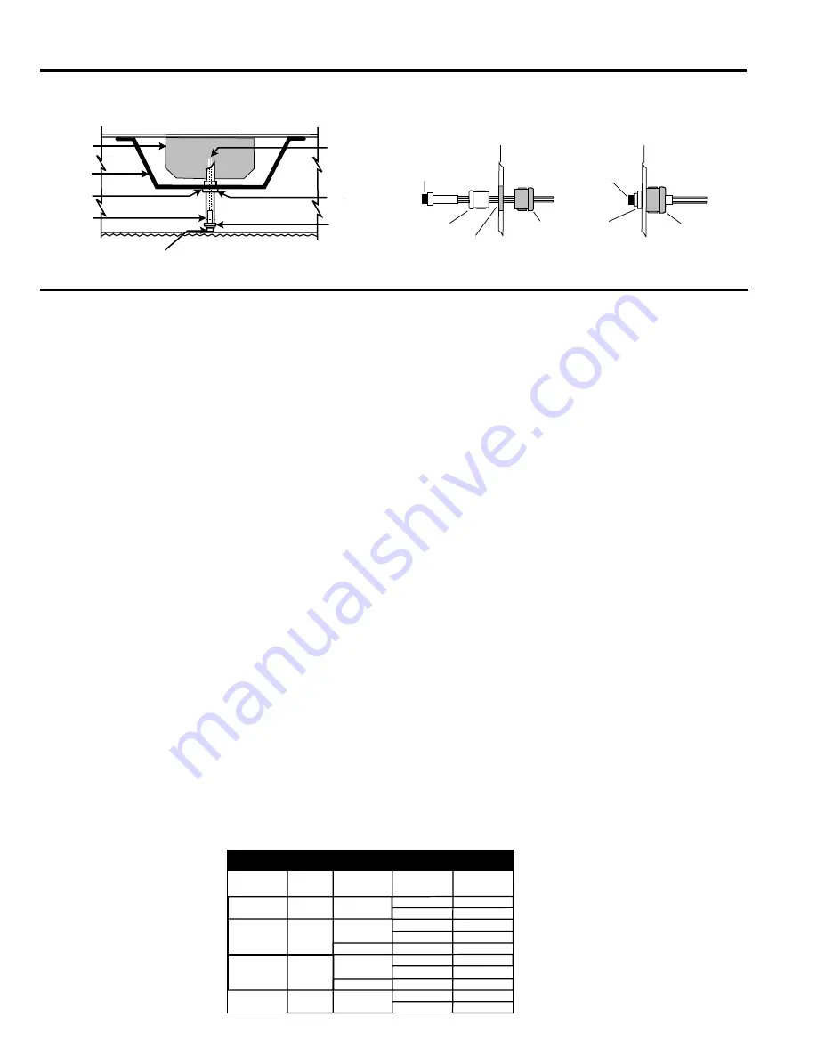
ILLUSTRATION 5
NOTE: After installing the charging indicator light and test switch, mark each with the appropriate label
6. After installation is complete, supply AC power to the emergency ballast and join the battery connector.
7. A short-term discharge test may be conducted after the emergency ballast has been charging for one
hour. Charge for 24 hours before conducting a long -term discharge test. Refer to OPERATION.
OPERATION
When AC power is applied, the charging indicator light is illuminated, indicating that the battery is being
charged. When power fails, the emergency ballast automatically switches to emergency power, operating
one or two lamps at reduced illumination for a minimum of 90 minutes.
MAINTENANCE
Although no routine maintenance is required to keep the emergency ballast functional, it should be checked
periodically to ensure that it is working. The following schedule is recommended:
1. Visually inspect the charging indicator light monthly. It should be illuminated.
2. Test the emergency operation of the fixture at 30-day intervals for a minimum of 30 seconds. Either one or two
lamps should operate at reduced illumination.
3. Conduct a 90-minute discharge test once a year. One lamp should operate at reduced illumination for at
least 90 minutes.
Refer any servicing indicated by these checks to qualified personnel.
Emergency
Ballast
Ballast
Channel
Cover
7/8" Punch
Plastic Tubing
(cut to necessary
length)
Charging Indicator Light
Leads to Charging
Indicator Light
7/8" Bushing
Inserted into
Ballast Channel
Cover
1/2" White Bushing
to Hold Charging
Indicator Light
TROFFER STYLE FIXTURE
Fixture
Indicator
Light
1/2" White
Bushing
5/8" Black
Bushing
Indicator
Light
Fixture
1/2" Punch
5/8" Black
Bushing
1/2" White
Bushing
STEP 1
STEP 2
STRIP STYLE FIXTURE
TABLE 1
LAMP
DIAMETER
1", 1-1/4", 1-1/2"
(T8, T10, T12)
1", 1-1/4", 1-1/2"
(T8, T10, T12)
LONG COMPACT
COMPACT
4-PIN (G24q)
4-PIN (2G11)
BASE
TYPE
POWER
(LENGTH)
NUMBER OF
LAMPS EMER.
BROWN
CONNECTOR
1
2
1
1
1
2
2
1
1
2
SINGLE OR
BIPIN
SINGLE OR
BIPIN
17-24W
32-40W (2'-4')
40-215W (5'-8')
18-39W
18-28W
40-50W
CLOSED
OPEN
CLOSED
OPEN
OPEN
CLOSED
OPEN
OPEN
CLOSED
OPEN
WIRING DIAGRAMS
FOR
1-LAMP
EMERGENCY OPERATION
EMERGENCY BALLAST AND AC BALLAST MUST BE FED FROM THE SAME BRANCH CIRCUIT
TYPICAL SCHEMATICS ONLY. MAY BE USED WITH OTHER BALLAST. CONSULT THE FACTORY FOR OTHER WIRING DIAGRAMS
A. ONE (1) LAMP RAPID START BALLAST
WARNING: Refer to Table 1 before connecting
BROWN
BROWN
RED
WHITE
BATTERY CONNECTOR
INDICATOR LIGHT
ORANGE
BLACK
BLUE
BLUE
BLU/WHT
WHITE
277V
120V
COM
BROWN -
TO UNSWITCHED AC
USE PROPER TAP
CAP UNUSED LEAD
EMERGENCY
BALLAST
1 LAMP
RAPID START
BALLAST
WHITE
BLACK
LINE
BLUE
RED
RED
YELL/BLK
YELLOW
RED
LAMP
BLUE
BLUE
BLU/WHT
BLU/WHT
BLU/WHT
WHITE
BLACK
LINE
BLUE
YELL/BLK
YELLOW
YELLOW
YELLOW
RED
WARNING: Refer to Table 1 before connecting
BROWN
BROWN
RED
OR
WHITE
BATTERY CONNECTOR
INDICATOR LIGHT
ORANGE
BLACK
BLUE
BLUE
BLU/WHT
WHITE
277V
120V
COM
BROWN -
TO UNSWITCHED AC
USE PROPER TAP
CAP UNUSED LEAD
EMERGENCY
BALLAST
1 LAMP
RAPID START
BALLAST
WHITE
BLACK
LINE
RED
YELL/BLK
YELLOW
RED
LAMP
C. ONE (1) LAMP INSTANT START SLIMLINE BALLAST
BLUE
BLUE
BLU/WHT
2 LAMP
SERIES
SEQUENCE
BALLAST
3 LAMP
RAPID START
ELECTRONIC
BALLAST
WHITE
BLACK
LINE
YELL/BLK
YELLOW
RED
RED
LAMP 2
LAMP 1
E. TWO (2) LAMP SERIES SEQUENCE INSTANT START BALLAST
WITH FOUR (4) LEADS
WARNING: Refer to Table 1 before connecting
WARNING: Refer to Table 1 before connecting
BROWN
BROWN
RED
WHITE
BATTERY CONNECTOR
INDICATOR LIGHT
ORANGE
BLACK
WHITE
277V
120V
COM
BROWN -
TO UNSWITCHED AC
USE PROPER TAP
CAP UNUSED LEAD
EMERGENCY
BALLAST
BROWN
BROWN
RED
RED
RED
WHITE
BATTERY CONNECTOR
INDICATOR LIGHT
ORANGE
BLACK
WHITE
277V
120V
COM
BROWN -
TO UNSWITCHED AC
USE PROPER TAP
CAP UNUSED LEAD
EMERGENCY
BALLAST
G. THREE (3) LAMP RAPID START ELECTRONIC BALLAST
LAMP 1
LAMP 2
LAMP 3
BLUE
BLUE
BLUE
BLU/WHT
2 LAMP
RAPID START
BALLAST
WHITE
BLACK
LINE
YELL/BLK
YELLOW
YELLOW
YELLOW
RED
RED
LAMP 2
LAMP 1
B. TWO (2) LAMP RAPID START BALLAST
D. TWO (2) LAMP LEAD/LAG INSTANT START SLIMLINE BALLAST
WARNING: Refer to Table 1 before connecting
BROWN
BROWN
RED
RED
WHITE
BATTERY CONNECTOR
INDICATOR LIGHT
ORANGE
BLACK
WHITE
277V
120V
COM
BROWN -
TO UNSWITCHED AC
USE PROPER TAP
CAP UNUSED LEAD
EMERGENCY
BALLAST
BLUE
BLUE
BLU/WHT
2 LAMP
LEAD LAG
BALLAST
WHITE
BLACK
LINE
YELL/BLK
YELLOW
RED
RED
LAMP 2
LAMP 1
WARNING: Refer to Table 1 before connecting
BROWN
BROWN
RED
WHITE
BATTERY CONNECTOR
INDICATOR LIGHT
ORANGE
BLACK
WHITE
277V
120V
COM
BROWN -
TO UNSWITCHED AC
USE PROPER TAP
CAP UNUSED LEAD
EMERGENCY
BALLAST
BLUE
BLUE
BLUE
BLU/WHT
2 LAMP
INSTART START
ELECTRONIC
BALLAST
WHITE
BLACK
LINE
YELL/BLK
YELLOW
RED
RED
LAMP 2
LAMP 1
WARNING: Refer to Table 1 before connecting
BROWN
BROWN
RED
WHITE
BATTERY CONNECTOR
INDICATOR LIGHT
ORANGE
BLACK
WHITE
277V
120V
COM
BROWN -
TO UNSWITCHED AC
USE PROPER TAP
CAP UNUSED LEAD
EMERGENCY
BALLAST
F. TWO (2) LAMP INSTANT START ELECTRONIC BALLAST
BLUE
BLUE
BLUE
BLUE
BLU/WHT
3
LAMP
INSTART START
ELECTRONIC
BALLAST
WHITE
BLACK
LINE
YELL/BLK
YELLOW
RED
RED
LAMP 3
LAMP 2
LAMP 1
WARNING: Refer to Table 1 before connecting
BROWN
BROWN
RED
WHITE
BATTERY CONNECTOR
INDICATOR LIGHT
ORANGE
BLACK
WHITE
277V
120V
COM
BROWN -
TO UNSWITCHED AC
USE PROPER TAP
CAP UNUSED LEAD
EMERGENCY
BALLAST
H. THREE (3) LAMP INSTANT START ELECTRONIC BALLAST
WIRING DIAGRAMS - for TWO-LAMP emergency operation
I. TWO (2) LAMP LEAD/LAG INSTANT START SLIMLINE BALLAST
BLUE
BLUE
BLU/WHT
2 LAMP
LEAD LAG
BALLAST
WHITE
BLACK
LINE
YELL/BLK
YELLOW
RED
RED
LAMP 2
LAMP 1
LAMP
WARNING: Refer to Table 1 before connecting
BROWN
BROWN
RED
WHITE
BATTERY CONNECTOR
INDICATOR LIGHT
ORANGE
BLACK
WHITE
277V
120V
COM
BROWN -
TO UNSWITCHED AC
USE PROPER TAP
CAP UNUSED LEAD
EMERGENCY
BALLAST
BLUE
BLUE
BLUE
BLU/WHT
2 LAMP
RAPID START
BALLAST
WHITE
BLACK
LINE
YELL/BLK
YELLOW
YELLOW
YELLOW
RED
RED
LAMP 2
LAMP 1
J. TWO (2) LAMP RAPID START BALLAST
WARNING: Refer to Table 1 before connecting
BROWN
BROWN
RED
RED
WHITE
BATTERY CONNECTOR
INDICATOR LIGHT
ORANGE
BLACK
WHITE
277V
120V
COM
BROWN -
TO UNSWITCHED AC
USE PROPER TAP
CAP UNUSED LEAD
EMERGENCY
BALLAST
K. ONE (1) WITHOUT AC BALLAST
BLUE
BLU/WHT
YELL/BLK
YELLOW
RED
WARNING: Refer to Table 1 before connecting
BROWN
BROWN
RED
CAP
CAP
WHITE
BATTERY CONNECTOR
INDICATOR LIGHT
ORANGE
BLACK
WHITE
277V
120V
COM
BROWN -
TO UNSWITCHED AC
USE PROPER TAP
CAP UNUSED LEAD
EMERGENCY
BALLAST
LAMP 1
LAMP 2
L. TWO (2) WITHOUT AC BALLAST
BLUE
BLU/WHT
YELL/BLK
YELLOW
RED
WARNING: Refer to Table 1 before connecting
BROWN
BROWN
RED
CAP
CAP
WHITE
BATTERY CONNECTOR
INDICATOR LIGHT
ORANGE
BLACK
WHITE
277V
120V
COM
BROWN -
TO UNSWITCHED AC
USE PROPER TAP
CAP UNUSED LEAD
EMERGENCY
BALLAST
WIRING DIAGRAMS - for EMERGENCY-ONLY fixtures


