background image

SureCall | 48346 Milmont Drive, Fremont CA 94538 | 1-888-365-6283 | sales@surecall.com

15

Installing your Hardware

Booster Hardware
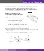
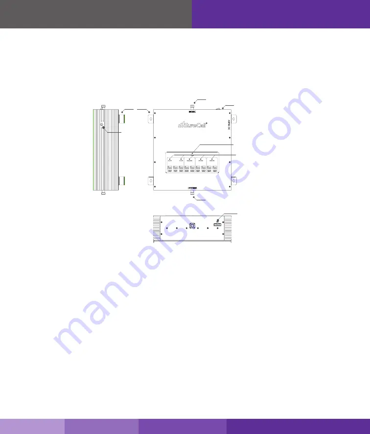
The following image shows the key hardware components on the cellullar booster.
Refer to this image as you install your Force5 kit components.

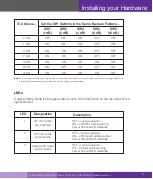
DIP Switches and Lights
The Force5 Industrial booster has the following indicators and controls:
•  PCS Uplink Warning light/DIP switches (1): These DIP switches control the PCS communications

with the cellular tower.

•  PCS Downlink Warning light/DIP switches (2): These DIP switches control the PCS amplification

within the building.

•  Power light (3): This light should be illuminated or blinking green at all times while the booster is

powered on.

•   Cellular Downlink Warning light/DIP switches 4): These DIP switches control the cellular

amplification within the building.

•  Cellular Uplink Warning light/DIP switches (5): These switches control the cellular communications

with the tower.

Power LED

N connector to inside antenna

N connector to outside antenna

Alert LED

Power Switch

 Programmer

Power Jack 

Mount Kit

Summary of Contents for Force5 Inline

Page 1: ...User Guide 2G 3G 4G Adjustable Five Band Signal Booster Kit Force5 ...

Page 2: ...2 SureCall 48346 Milmont Drive Fremont CA 94538 1 888 365 6283 sales surecall com ...

Page 3: ...the Outside Anntenna Pg 10 11 Installing the Insides Anntenna Pg 12 13 Installing Signal Booster Pg 14 15 Configure Gain Setting Pg 16 18 Troubleshooting Pg 19 Specification Pg 20 Kitting Information Pg 21 Warranty Pg 22 23 Safety Information Pg 23 Table of Contents SureCall 48346 Milmont Drive Fremont CA 94538 1 888 365 6283 sales surecall com 3 ...

Page 4: ... slow data rates by amplifying incoming and outgoing cellular signals in homes and offices 25 000 square feet and up to 100 users Force5 enhances 2G 3G voice and 4G reception data for all major U S carriers If you need any assistance while installing this product please contact tech support at 1 888 365 6283 or email us at support surecall com SureCall 48346 Milmont Drive Fremont CA 94538 1 888 36...

Page 5: ... Force5 works with two or more antennas Up to four inside antennas that communicate with your cell phone An outside antenna that communicates with the cell tower Signals sent from a cell tower are received by the outside antenna amplified by the booster and then broadcast to your phone via the inside antenna When your phone transmits the signal is sent to the inside antenna amplified and then sent...

Page 6: ...g the inside antenna to the signal booster One power supply Note Force5 is available in four standard kits that are customized to your particular needs Other kit options available include additional dome or panel antennas cables and splitters For more information see our website or email us at sales surecall com Due to the recent change of our company name from Cellphone Mate CM to SureCall SC we ...

Page 7: ...1 interior panel antenna 30 and 75 SC 400 coax cables For a detailed description see Kitting Information on page 21 SC 248W Omni Antennas are ideal for topographies with minimal obstacles They offer 360 hemispherical coverage Yagi antennas are for targeted areas and are capable of reaching cell towers up to 30 miles away Dome antennas are for a central location and offer 360 coverage Panel Antenna...

Page 8: ...de and inside antenna cables to the signal booster and connect the booster to an AC power source See page 14 15 for instruction if needed Step 5 Configure gain settings on the signal booster if needed See page 18 for instruction if needed Before You Install Outside Omni Force5 Inside Domes Outside Omni FCC 27 5 d 4 Statement Fixed mobile and portable hand held stations operating in the 1710 1755 M...

Page 9: ...the outside antenna find the area with the strongest cellular signal source from your service provider by following the directions below You can also go to www antennasearch com to find the general location of your carrier s towers Measure the strength of the existing cellular signal in various locations Apple iPhones Dial 3001 12345 and press Call In the top left corner a number appears instead o...

Page 10: ...tions and other radiating elements 3 If the mounting area is prone to weak cellular signals or if the density of the roof and ceil ing partially block the signal the booster will operate at its default setting of 65 dB gain be sure to place the outside antenna at least 75 feet from the inside antenna for best performance 4 Do not co locate antennas or operate the outside antenna with any other ant...

Page 11: ... or marker Step 3 Unscrew nut on end of stucco screw and remove it along with lock washer and regular washer Step 4 Place vertical plate into desired location and tap the screws head first along with sleeve into stucco 1 2 to 5 8 deep into place Step 5 In this order place washer lock washer and nut on each screw and tighten until secure When tightening screw sleeve will expand to secure plate Scre...

Page 12: ...nd flat panel versions Installing Your Hardware Note As you can see from the table above acquiring the recommended inside and outside antenna separation optimizes coverage significantly Any reduced antenna separation reduces the booster s coverage Note See next page for outside antenna installation details Required Between Outside and Inside Antenna Antenna Separation Table antenna separation 40dB...

Page 13: ...stic antenna is an omni directional interior antenna that gathers signals from all sides Range of antenna is dependent on three factors 1 physical obstructions 2 power generated by booster and 3 reception from out side signal received and distributed by outside antenna Besides the antenna itself parts include mounting equipment for either a flat horizontal surface or a wall It should be mounted in...

Page 14: ...oster connector marked OUTSIDE Hand tighten the connection 5 Connect the inside antenna cable to signal booster marked INSIDE Hand tighten the connection 6 Connect the AC power cord to the signal booster 7 Connect the plug on the other end of the 110V AC power outlet 8 Turn the booster s power switch on The signal booster turns on automatically The Power LED lights up to show that the signal boost...

Page 15: ...ol the PCS communications with the cellular tower PCS Downlink Warning light DIP switches 2 These DIP switches control the PCS amplification within the building Power light 3 This light should be illuminated or blinking green at all times while the booster is powered on Cellular Downlink Warning light DIP switches 4 These DIP switches control the cellular amplification within the building Cellular...

Page 16: ...To change it move the DIP switches to the ON or OFF position Moving a switch down away from the LEDs turns OFF the switch and increases booster gain for the selected channel Moving a switch up toward the LEDs turns ON the switch and decreases booster gain for the selected channel Switch settings are cumulative This means the total amount of attenuation for a channel equals the combined dB of all D...

Page 17: ...ink and Downlink LTE 781 Uplink and Downlink Cellular 800 Uplink and Downlink OFF normal operation ON LTE AT T uplink warning Power off booster immediately OFF normal operation ON LTE Verizon uplink warning Power off booster immediately OFF normal operation ON Cellular uplink warning Power off booster immediately Designation Description 15 DB 21 DB 31 DB ON ON ON ON ON ON ON OFF ON ON OFF ON OFF O...

Page 18: ...ffected side shuts down after 30 seconds In general the cellular side oscillates more easily than the PCS side 4 The booster wakes up and Power LED 3 turns green If oscillation resumes the LEDs flash as described previously These 30 second cycles continue for 15 minutes or until the problem is resolved 5 If the problem is not resolved within 15 minutes the booster shuts down automatically all LEDs...

Page 19: ...e outside signal as close as you can to the outside antenna see instructions on page 7 Double check all signal booster and antenna cable connections Be sure your signal booster s dB gain is turned up to full power on each dial see apge 14 Each SureCall signal booster is equipped with Auto Shutdown to prevent cell tower interference The outside antenna may be close to a cell tower Move the outside ...

Page 20: ...e Fremont CA 94538 1 888 365 6283 sales surecall com Your signal booster has no power Verify that the switch on the power supply is turned on and red LED is ON Connect the power supply to an alternate power source Be sure the power source is not controlled by a switch that can remove power from the outlet Check the green POWER LED on the signal booster If it is OFF return the power supply to SureC...

Page 21: ... 11 dBi SC 400 75NN 75 Feet 10 dBi 4 41dB 6 17dB 6 54 dB SC 248W 4 22dB 7 dBi 10 dBi 10 dBi SC 222W 7 dBi 3 dBi 3 dBi 6 dBi 6 dBi 2 05dB SC 400 30NN 30 Feet 2 12 dB 2 83 dB 2 98 dB Outside Cable Inside Antenna Inside Cable Gain Loss LTE A Verizon ATT 700 Mhz AWS T Mobile 1700 2100 MHz Cellular 800 MHz PCS 1900 MHz Product Number Description Description Note Due to the recent change of our company ...

Page 22: ...pecifications The limit of liability under this warranty is at SureCall s option to repair or replace any product or part thereof which was purchased up to THREE YEARS after May 1 2014 or TWO YEARS for products purchased before May 1 2014 as determined by examination by SureCall prove defective in material and or workmanship Warranty returns must first be authorized in writing by SureCall Disassem...

Page 23: ...ons hereof SAFETY INFORMATION This is a CONSUMER device BEFORE USE you MUST REGISTER THIS DEVICE with your wireless provider and have your provider s consent Most wireless providers consent to the use of signal boosters Some providers may not consent to the use of this device on their network If you are unsure contact your provider You MUST operate this device with approved antennas and cables as ...

Page 24: ...nt generates uses and can radiate radio frequency energy and if not installed and used in accordance with the instructions may cause harmful interference to radio communications However there is no guarantee that interference will not occur in a particular installation If this equipment does cause harmful interference to radio or television reception which can be determined by turning the equipmen...

Reviews: