


SureCall | 48346 Milmont Drive, Fremont CA 94538 | 1-888-365-6283 | sales@surecall.com
13
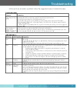
Troubleshooting
In the event you encounter a problem, follow the suggestions below to resolve the issue.
SureCall | 48346 Milmont Drive, Fremont CA 94538 | 1-888-365-6283 | sales@surecall.com
13
Troubleshooting
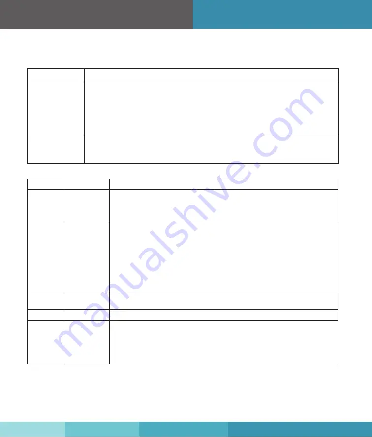
Problem
Resolution
Signal booster has no
power
Verify that the switch on the power supply is turned on and red LED is ON.
Connect the power supply to an alternate power source.
Be sure the power source is not controlled by a switch that can remove power from the outlet.
Check the green POWER LED on the signal booster. If it is OFF, return the power supply to SureCall.
Contact tech support at
1-888-365-6283 or support@surecall.com, or go to www.surecall.com and log on to online support to
receive an RMA.
After installing your
signal booster
system, you have no
signal or reception.
Cable connections should be tightly fitted to the booster and antenna.
There should be no flashing or solid red LEDs as well as no lights flashing rapidly between two colors.
Be sure your signal booster’s dB gain is turned up to full power on each dial.
LED Indicators
LED Color
LED Condition
Resolution
Red
Solid
Band is off.
If a red light has been flashing for an extended time, the band will automatically shut off and
display a solid red light.
This can also happen when the booster attenuation has been turned all the way down.
Red
Flashing
Indicates that the booster is receiving too much signal which could cause the affected band
to automatically turn off. When this happens:
1. For kits using an OMNI outside antenna, relocate the outside antenna to a location
where the signal is weaker.
2. For kits using a YAGI outside antenna, turn the antenna in short increments away from
the signal source.
3. Increase the separation between antennas (additional vertical separation works best).
4. Add an inline attenuator to the cable coming into the outside port of the booster.
5.
As a last resort, turn down the dB gain on the dial until the light goes OFF or flashes
yellow.
Yellow
Flashing
Indicates that the Automatic Gain Control (AGC) is self-adjusting. This is part of normal
operation.
Yellow
Solid
Indicates that the band is inactive. Light is off while band is active.
Yellow/Red
Alternately
Flashing
Oscillation is detected.
First, try increasing the separation between the inside and outside antennas. If your booster
kit uses two directional antennas (example: outside Yagi antenna and inside panel antenna),
ensure that they are facing away from one another.
If oscillation continues, lower the dB gain in small increments until the light turns off or flashes
yellow.


