


SureCall, Inc | 1-888-365-6283 | support@surecall.com | www.surecall.com
13
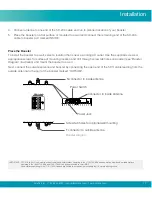
Installation
LED Indicators
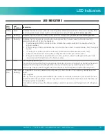
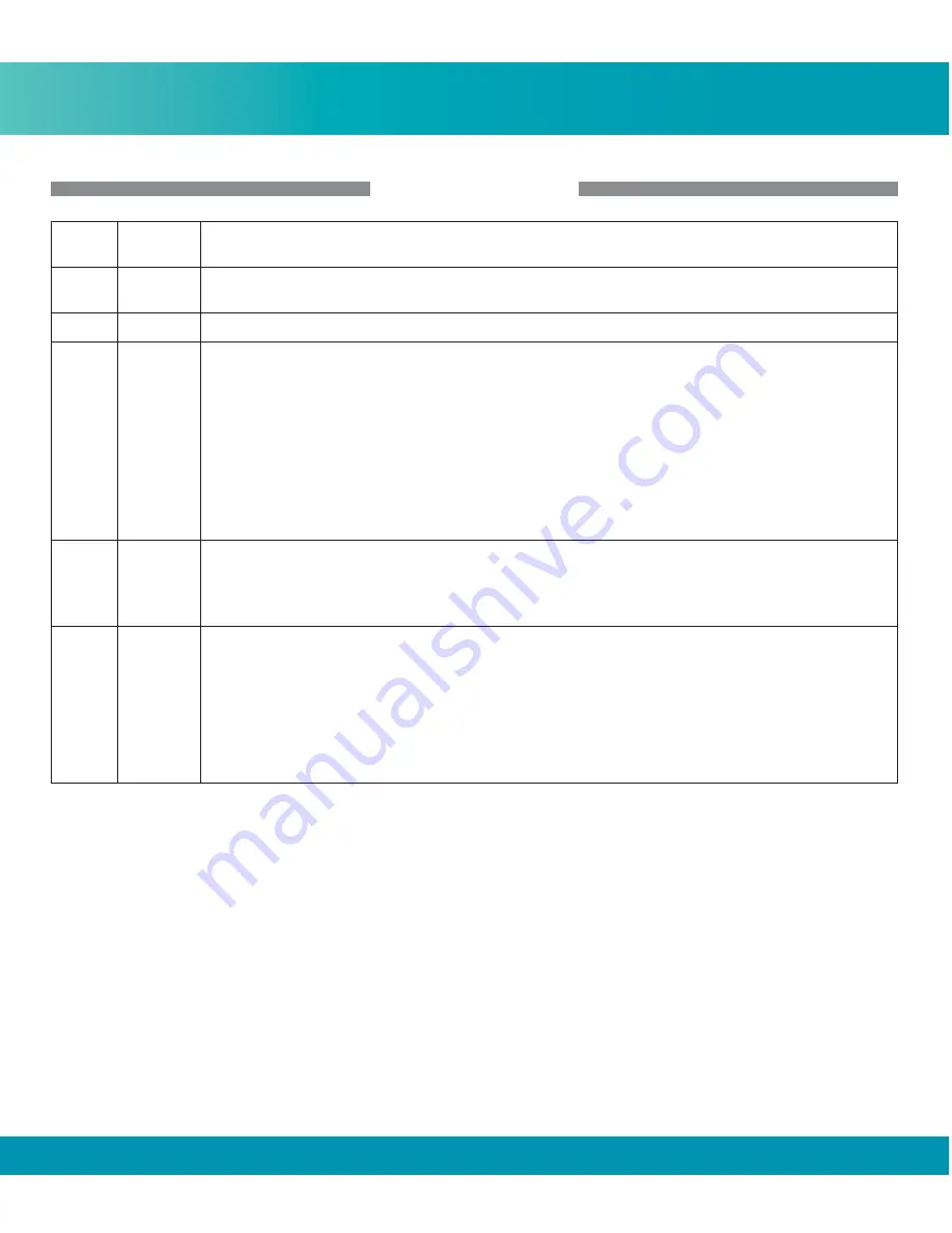
LED INDICATORS
LED
Color
LED
Condition Resolution
Yellow
Solid
Indicates that the frequency band is not being used. After a period of time, if there’s no activity, that
band will go into sleep mode. Light is off while band is active.
This is part of normal operation.
Yellow Flashing
Indicates that the Automatic Gain Control (AGC) is self-adjusting.
This is part of normal operation.
Red
Flashing
Indicates that the booster is receiving too much signal which could cause the affected band to
automatically turn off. When this happens:
1. For kits using an OMNI outside antenna, relocate the outside antenna to a location where the
signal is weaker.
2. For kits using a YAGI outside antenna, turn the antenna in short increments away from the signal
source.
3. Increase the separation between antennas (additional vertical separation works best).
4. Add an inline attenuator to the cable coming into the outside port of the booster.
5. Though not desirable as amplification will not be optimum, lower the dB gain setting in small
increments until the light turns off or flashes yellow.
Red
Solid
The frequency band is off.
If a red light has been flashing for an extended time due to too much signal, that frequency band will
display a solid red light indicating that the circuitry for that frequency band has been turned off.
This can also happen when the gain dial for a frequency band has been turned all the way down.
Yellow/
Red
Alternately
Flashing
Self-oscillation has been detected and to prevent it, one or more of the frequency bands have shut
down.
If this happens:
First, try increasing the separation between the inside and outside antennas. If your booster kit uses
directional antennas (example: outside Yagi antenna and inside panel antenna), ensure that they are
facing away from one another.
If condition continues, lower the dB gain setting in small increments until the light turns off or flashes
yellow.


