background image

DLD8080 R4.30 & R4.31 Manual

Delayline Detector

DLD8080

(Release 4.30 & 4.31)

Manual

Summary of Contents for Delayline DLD 8080

Page 1: ...DLD8080 R4 30 R4 31 Manual Delayline Detector DLD8080 Release 4 30 4 31 Manual...

Page 2: ...ny phone 49 6131 62716 0 fax 49 6131 62716 29 email info surface concept de web www surface concept de All rights reserved No part of this manual may be reproduced without the prior permission of Surf...

Page 3: ...4 1 1 Start Up Procedure 12 4 1 2 Dark Count Rate Measurement 14 4 1 3 Standard DLD Operation 14 4 2 Standard Operation Procedure 15 4 2 1 Operation with MCP Front Side terminated to GROUND 15 4 2 2...

Page 4: ...nics ACU 3 4 2 26 7 1 1 Positions of the Discriminator Threshold Regulators 27 8 Micro Channel Plate MCP 28 8 1 Specifications 28 8 2 Storage 28 8 3 Handling 28 8 4 Operation 29 8 5 MCP Lifetime and O...

Page 5: ...5 DLD8080 R4 30 R4 31 Manual DLD8080 R4 30 R4 31 Manual Surface Concept GmbH...

Page 6: ...ganyelectricalorelectronicoperations and strictly follow the safety rules given within this manual The following symbols appear throughout the manual Note The notesymbol markstextpassages whichcontain...

Page 7: ...ses on the measurement of time differences and time sums of signals with a high temporal resolution in one device The count rate can reach several MHz in the commonly used 4 fold coincidence measureme...

Page 8: ...he DLD8080 R4 30 R4 31 Detector The detector is transported under vacuum Proceed as follows to install the detector into your vacuum chamber Vent the transport container carefully and slowly use N2 fo...

Page 9: ...of the detector A storage time of one month should not be exceeded The transport housing should be evacuated regularly with a period of at least one month in case that the transport housing must be us...

Page 10: ...3 SHV feedthroughs for the high voltage supply of the detector named MCP F MCP B and U_DLD The naming can be found directly engraved on the CF40 flange MCP F is the contact to the front side of the M...

Page 11: ...sarily part of each detector delivery Further information about detector operation voltages can be found in chapter 4 Install the hardware drivers and the GUI DLD software See the GUI DLD Software Ins...

Page 12: ...end user software manual Be sure that the vacuum pressure at the detector is remarkably below 1E 6mbar otherwise the micro channel plates might be damaged by a local discharging in general the lower t...

Page 13: ...to the MCP front voltage MCP F The Surface Concept HV Power Supply keeps the relation between MCP B and U_ DLD fixed at 400V automatically and the MCP F voltage corresponds directly to the externalre...

Page 14: ...harply bounded See Figure 4 for an example your specific DLD image can differ in size shape and segmentation Figure 4 Example for DLD image of accumulated dark counts 4 1 3 Standard DLD Operation Afte...

Page 15: ...heet of the detector Watch the vacuum pressure while increasing the high voltage turn the voltages back if an unusual increase is observed in the pressure indicator for high voltage sparking High volt...

Page 16: ...high voltage applied to MCP F for the first time Otherwise turn up the high voltage carefully and stepwise within a couple of minutes to the operation voltage The voltage increase should not exceed 4...

Page 17: ...ramp time of 5 min should be used to increase MCP B to 1 400V MCP F MCP B In parallel U_DLD must be ramped to a voltage of 1 800V MCP B 400V always keeping a voltage difference between MCP B and U_DL...

Page 18: ...ell as any HV cabling and SHV termination plugs Windows and feedthroughs should be wrapped with aluminum foil to protect them from rapid temperature changes The use of heating tapes and jackets is not...

Page 19: ...the delayline by capacitive coupling The pulses are traveling to the both ends of the meander within a time determined by the hitting position Each hit position is encoded by a fast data acquisition...

Page 20: ...four time measurements tx1 tx2 ty1 ty2 may be a good choice as well The results of all those time sums correspond to t sum t offset t hit where t hit is the interesting time e g ToF in a given experi...

Page 21: ...cted by the electronics independent on the intensity of the electron source e g mercury lamp On the other hand if the MCP voltage and or the intensity of the electron source are too high the detector...

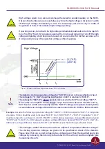
Page 22: ...see Figure 8 The MCP voltage should only be increased to compensate a decrease in amplification of the MCP stack do to degradation MCPs degradation is recognizable by a slow permanent decrease of the...

Page 23: ...than one decade starting from the 10 10mbar range for new MCPs being operated with a load of a couple of million counts per second The effect of outgassing reduces with operation time of the detector...

Page 24: ...ives a schematic orientation of the X and Y meanders Signal readout is done via two readout lines named 1 and 2 for each meander structured delayline The naming of the readout lines is put together of...

Page 25: ...voltage connection for the delayline detector is given schematically in Figure 11 The third CF40 flange is a spare port for future extensions on the detector e g additional pulse readout of the MCP st...

Page 26: ...l Converter The ACU 3 4 2 contains pulse amplifiers pulse shapers and constant fraction discriminators 1 4x SMB sockets for signal transfer from SMB feedthrough 2 Hole for orientation pin from SMB fee...

Page 27: ...rtifacts within the image increased dark count rate etc The readout electronics is adjusted to its best performance to the operation voltage of the detector when delivered A new adjustment should not...

Page 28: ...lid glass border Use clean degassed tools fabricated from stainless steel Teflon or other ultra high vacuum compatible materials Handling MCPs should be limited to trained experienced personnel MCPs w...

Page 29: ...aterials which raise the work function of the surface causing gain degradation Operation at higher temperatures 50 C will cause gain degradation MCPs can degas for quite a while during operation The p...

Page 30: ...e increased to compensate gain degradation over time This voltage is given in the specification sheet of each detector A typical behavior of the detector voltage increase over time to compensate gain...

Page 31: ...inning of the area of operation The new value for the operation voltage should be a bit above the position of the change in the slope Figure 16 shows an example of a MCP curve with the specified opera...

Page 32: ...ler count rate should now be much smaller The detector will be delivered already pre conditioned Unfortunately the degas procedure must be started anew to a certain extend after each venting of the de...

Page 33: ...R4 31 Manual Consult the Hints_and_TroubleShootingDLDs Manual part of the detector delivery in case of any problems prior to contacting your provider 9 Troubleshooting DLD8080 R4 30 R4 31 Manual Surf...

Page 34: ...ector VoltageatMCPFront VoltageDifferencebetweenMCPBackandAnode GridVoltage Bake OutTemperature max VacuumPressureRangeforOperation Delayline Detector General 4 1 6GHz 200MHz 20ps 50ps whileambienttem...

Page 35: ...oltage on the MCPs and b an undervoltage at high count rates 22 Figure 9 Schematic orientation and naming of delaylines and DLD image 24 Figure 10 Connection ports of the DLD8080 R4 30 R4 31 25 Figure...

Page 36: ...normative documents where relevant EN 61000 6 2 2005 AC 2005 Electromagnetic compatibility EMC Generic standards Immunity for industrial environments EN 61000 6 4 2007 A1 2011 Electromagnetic compati...

Reviews: