11
DLD8080 R4.30 & R4.31 Manual
• Terminate the external reference input “HV Ref. In” of the high voltage power supply with the SHV
termination plug (part of the delivery). Later on also a reference voltage (e.g. the column potential in an
electron microscope or the Herzog potential in an electron spectrometer) can be applied to the front
side of the MCP stack of the detector as well as to the high voltage power supply (see the manual for
the high voltage power supply for more details).
Note
In cases that no reference voltage is applied to the MCP front, the termination plug must
be used to ground the MCP front. Otherwise the MCP stack is not functioning as the
reference potential is missing.
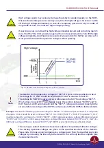
The exact operation voltage of the detector is given in the specification sheet. It is given
in reference to the “MCP-F” potential.
Note
HV power supplies always produce some noise level on the HV lines. An increased
noise level can lead to a significant loss of spatial and time resolution. In such a case an
appropriate noise filter between the HV power supply and the DLD HV connectors is
highly recommended.
HV power supplies as part of the DLD delivery have been explicitly tested for the DLD
operation.
For the use with a customer HV supply there are noise filters available from Surface
Concept. They are not necessarily part of each detector delivery.
• Further information about detector operation voltages can be found in chapter 4.
• Install the hardware drivers and the GUI – DLD software. See the GUI – DLD Software Installation manual
for further details.
• Connect the power cable to the main connector of the TDC and use the USB cable to connect the TDC
to the PC. Do not use PC front panel USB connectors; they are often restricted in performance.
• To perform time measurements with respect to an external clock, provide start pulses to the start
input of the TDC. Use the corresponding BNC socket of the TDC (see the TDC manual for the specific
connection scheme of the TDC).
3.2.4 Software Interface and Installation
All operation functions for data readout of the detector package are encapsulated in a dynamic linked
library(either “delayline_gpx3.dll” or scTDC1.dll). Data processing and presentation on the PC is realized
by an enduser software (e.g. GUI). See the corresponding software manual for detailed information on the
software package and the DLL interface.
The delivery package of the delayline detector includes a CD-ROM with hardware drivers and the GUI
software. Insert the CD into your disk drive and install the software package as described in the DLD - GUI
Software Installation Manual.
Read-out of the delayline detector is done via the USB port of the TDC (time-to-digital-converter). The
specific PC system requirements can be found in the corresponding TDC manual.
DLD8080 R4.30 & R4.31 Manual | Surface Concept GmbH


