21
DLD8080 R4.30 & R4.31 Manual
5.3 Data Acquisition
Each readout line of the detector anode is connected to a fast amplifier followed by a constant fraction
discriminator (CFD) for pulse shaping. They are encapsulated inside the pulse processing electronics (ACU
= Amplifier-CFD-Unit or AU = Amplifier-Unit). The main function of the CFD is digital pulse discrimination,
ideally without any time-walk even at varying pulse heights. A time-to-digital converter (TDC) behind
these chains serves as stop-watch for arrival time measurements. The measurement results, in terms of
differences and sums are fed into the PC via a USB 2.0 interface and are completed to 2D images (with
or without time stamps) by the histogram module of the data acquisition DLL. Data processing and
presentation on the PC is realized by the end-user software (see the corresponding software manuals for
detailed information on the software package).
5.4 Working with the DLD - Important Details
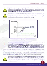
The DLD is a counting system that works in a laterally resolving sense by detecting four pulses from the
four ends of the delayline meanders in a fourfold coincidence. It only works correctly within a certain range
of the supply voltage. The MCP voltage has to exceed an operation threshold for the detector otherwise
the pulse detection is not possible. This is due to the induced pulses on the delayline which have to reach
a certain amplitude to be detected by the electronics, independent on the intensity of the electron source
(e.g. mercury lamp).
On the other hand, if the MCP voltage and/or the intensity of the electron source are too high, the detector
overloads and again pulse detection is not possible. Saturation effects of the MCPs limit the amount of
electrons provided by single pulses. An intensity increase of the electron source leads to an increased
number of hits on the MCP. The current per bunch and therefore the amplitude for the single pulses
decreases. There are two kinds of overloads: local and global. A local overload (locally high intensity on the
MCP) leads to reduced count rate within this local area and to “darkened” areas in the images. An intensity
too high and homogeneously distributed over the whole MCP first leads to diffuse images and then (with
further increasing intensity) to randomly distributed artificial structures up to nearly no count rate at all
(global overload).
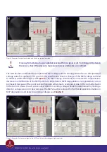
Figure 7
shows examples of a partial and a global overload. Pulse amplitudes that are too low to be
detected by the electronics are the explanation for the effects for a local overload. The explanation for
those overload effects is mainly the loss of the fourfold coincidence condition of an incoming event and a
fitting fourfold coincidence of random pulses, respectively. High intensities on the MCPs always lead to a
significant pressure increase. Therefore an observed pressure increase can always be taken as an indicator
for an overload of the detector, when problems with the functionality of the DLD occur.
DLD8080 R4.30 & R4.31 Manual | Surface Concept GmbH


