background image


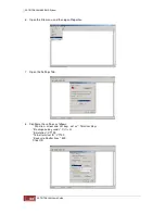
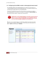
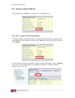
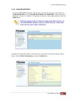
NOTE: For NAS system usage, if you want the maximum capacity allowed to be 
over 2TB and to have a single Volume Set over 2TB, select the “64bit LBA” option.


16TB max Volume Set recommended.
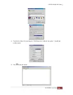
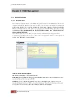
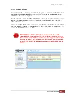


Click  on  the 

Confirm  The  Operation 

opti on  and  click  on  the 

Submit 

button  in  the  Quick 

Create screen. The Raid Set and Volume Set will start to initialize. 
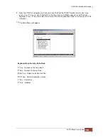
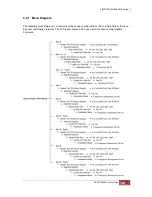
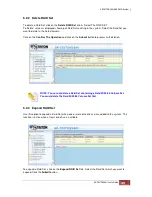
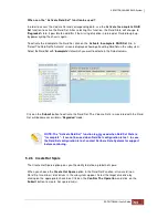
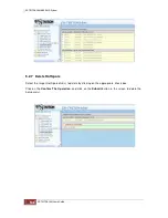
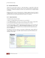
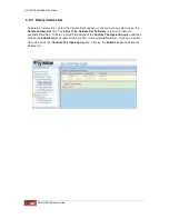
 

You can use 

RaidSet Hierarchy 

feature to view the Volume Set information (Refer to Section 

5.6.1). 

 
NOTE: In Quick Create your Raid Set is automatically configured based on the 
number of disks in your system. Use the Raid Set Function and Volume Set 
Function if you prefer to customize the Raid Set and Volume Set. 


Summary of Contents for TRITON 16Ni

Page 1: ...SurfRAID TRITON 16Ni User s Guide Revision 1 1...

Page 2: ...verview 2 1 Packaging Shipment and Delivery 2 2 Unpacking the NAS System 2 3 Identifying Parts of the SR TRITON16Ni System 2 3 1 Front View 2 3 2 Rear View Chapter 3 Getting Started with the SR TRITON...

Page 3: ...ume Set Migration 5 3 5 Check Volume Set 5 3 6 Schedule Volume Check 5 3 7 Stop Volume Check 5 4 Physical Drive 5 4 1 Create Pass Through Disk 5 4 2 Modify a Pass Through Disk 5 4 3 Delete Pass Throug...

Page 4: ...ating System Management GUI Chapter 8 SR TRITON16Ni proNAS Manager 8 1 Volume Manager 8 1 1 Volume Group Management 8 1 1 1 Create the proNASVG Volume Group 8 1 1 2 Creating another Volume Group 8 1 1...

Page 5: ...4 Share Manager 8 4 1 Share Management 8 4 1 1 Creating a New Share 8 4 1 2 Applying ACL 8 4 1 3 Modifying a Share 8 4 1 4 Deleting a Share 8 4 2 Properties Setting 8 4 2 1 Steps to Make a Share Folde...

Page 6: ...0 1 Introduction to SR TRITON16Ni proBackup Utility 10 2 Administrator Logon 10 3 Create Backup Plan 10 4 Restore Backup 10 5 Account Detail Chapter 11 proNAS HA Optional Feature 11 1 Introduction to...

Page 7: ...nual uses section numbering for every topic being discussed for easy and convenient way of finding information in accordance with the user s needs The following icons are being used for some details a...

Page 8: ...there is no guarantee that interference will not occur in a particular installation If this equipment does cause interference to radio or television equipment reception which can be determined by tur...

Page 9: ...removed from the enclosure Outlets must be accessible to the equipment All external connections should be made using shielded cables and as much as possible should not be performed by bare hand Using...

Page 10: ...xible and expandable application and together with the proNAS management solution proNAS High Availability and proBackup client backup solution provide businesses with the most flexible scalable secur...

Page 11: ...line capacity expansion within the enclosure Support spin down drives for power saving MAID and disk drive power cycle Scheduled volume check data correctness for RAID 3 5 6 64 bit Linux based embedde...

Page 12: ...ID connection to a Host System volume created from enclosure is used by other host system One 1 4X SAS Expansion port for JBOD connection up to 6 SAS JBOD enclosures max 112 disks using SR TRITON16JS3...

Page 13: ...nicode support Multi node Management GUI proNAS Data and Configuration Backup Central Management Networking Supports NIC Trunking types Fault Tolerant Load Balance Fault Tolerant and Load Balance and...

Page 14: ...Replication Requires two SR TRITON16Ni subsystems Duplication Scheduling Rsync Replication proBackup backup from client to NAS and Symantec Backup Exec RALUS agent for Linux Support CDP Server Option...

Page 15: ...pes should be used Most operating systems today support concurrent disk I O operations across multiple drives However in order to maximize throughput for the disk subsystem the I O load must be balanc...

Page 16: ...n there is less performance degradation during drive failure than in RAID 5 arrays RAID 3 sector stripes data across groups of drives but one drive in the group is dedicated for storing parity informa...

Page 17: ...tween the increased data availability inherent in RAID 1 and RAID 5 and the increased read performance inherent in disk striping RAID 0 These arrays are sometimes referred to as RAID 0 1 or RAID 1 0 a...

Page 18: ...mance RAID 5 combines efficient fault tolerant data storage with good performance characteristics However write performance and performance during drive failure is slower than with RAID 1 Rebuild oper...

Page 19: ...tion of RAID levels 0 and 1 This level provides striping and redundancy through mirroring RAID 10 requires the use of an even number of disk drives to achieve data protection while RAID 1E Enhanced Mi...

Page 20: ...Set then the capacity of the smallest disk will become the effective capacity of all the disks in the Raid Set 1 4 2 Volume Set A Volume Set is seen by the host system as a single logical device It is...

Page 21: ...ve Support The RAID subsystem has built in protection circuit to support the replacement of SATA II hard disk drives without having to shut down or reboot the system The removable hard drive tray can...

Page 22: ...re you purchased the subsystem for further instructions 2 2 Unpacking the NAS System The package contains the following items SR TRITON16Ni NAS SAS SATA RAID System chassis Two 2 power cords Three 3 C...

Page 23: ...ction HDD Status LED Green LED indicates power is on and hard drive status is good for this slot If hard drive slot or the hard drive has failed the LED is orange HDD Access LED This LED will blink bl...

Page 24: ...the previous menu NOTE This button can also be used to reset the alarm beeper For example if one power supply fails pressing this button will mute the beeper 6 Environment Status LEDs 7 Disk Tray Par...

Page 25: ...PSU 2 are located at the rear of the SR TRITON16Ni system If the power supply fails to function the Power Fail LED will turn red and an alarm will sound An error message will also appear on the LCD sc...

Page 26: ...tions and Com2 is for UPS serial cable 11 SAS Expansion Port Use this to connect SAS JBOD expansion enclosures to expand the storage capacity of the SR TRITON16Ni Up to 6 SR TRITON16JS3 JBOD enclosure...

Page 27: ...er environments Typically this has already been done by Partners Data Systems along with the data RAID volumes and can be skipped to the next step After initially setting up the internal RAID controll...

Page 28: ...eed to be shutdown via the proNAS management interface first then expansion chassis power switches 1 Plug in the 2 power cords into the AC power input sockets located at the rear of the SR TRITON16Ni...

Page 29: ...ation paperwork on top of your storage system All disk drives will be labeled with unit of chassis and drive slot Only the cold shelf spare labeled disk drives should be left out of the storage system...

Page 30: ...chassis and insert the other end to the SAS In port of the JBOD enclosure JBOD 1 2 If there are additional JBOD enclosures to be connected connect other 1m external SAS cable from the SAS Expansion Po...

Page 31: ...nto place 4 Ensure all the external SAS cabling is fully seated and locked Only 1 meter external SAS cabling should be used to connect JBOD expansion subsystems 5 Power on all the JBOD subsystems star...

Page 32: ...han one method at the same time The R Link Ethernet port will be needed to support remote notification and is strongly recommended 4 1 Configuration through VT100 Terminal Configuring through a termin...

Page 33: ...4 The default setting of the monitor port is 115200 baud rate 8 data bit non parity 1 stop bit and no flow control 5 Click disconnect button...

Page 34: ...pen Properties 7 Open the Settings Tab 8 Configure the settings as follows Function arrow and ctrl keys act as Terminal Keys Backspace key sends Crtl H Emulation VT100 Telnet terminal ID VT100 Back sc...

Page 35: ...ubsystem and Terminal together Press X key to display the internal RAID array Monitor Utility screen on your VT100 Terminal 10 The Main Menu will appear Keyboard Function Key Definitions A key to move...

Page 36: ...ws user to set or clear the RAID subsystem s password protection feature Once the password has been set the user can only monitor and configure the RAID subsystem by providing the correct password The...

Page 37: ...sts of all physical disks installed Raid Set Functions Create a customized Raid Set Volume Set Functions Create a customized Volume Set Physical Drive Functions View individual disk information Raid S...

Page 38: ...t password is set to 00000000 Function Key Definitions The four function keys at the top of the front panel perform the following functions Parts Function Up and Down Arrow buttons Use the Up or Down...

Page 39: ...Diagram The following menu diagram is a summary of the various configurations and setting functions that can be accessed through terminal The LCD panel menus also have similar functions except Update...

Page 40: ......

Page 41: ......

Page 42: ......

Page 43: ......

Page 44: ...rom remote machine and enter in the address bar http IPAddress The internal RAID manager IP address is displayed on the front panel LCD IMPORTANT The R Link default IP Addressis set to DHCP otherwise...

Page 45: ...ns Create customized and edit existing Raid Sets Volume Set Functions Create customized Volume Sets and allow modification of parameters of existing Volume Sets parameter Physical Drive Create pass th...

Page 46: ...RAID Set when creating RAID Sets If the Volume Set size is over 2TB an option Greater Two TB Volume Support will be automatically provided in the screen as shown in the example below There are three o...

Page 47: ...on and click on the Submit button in the Quick Create screen The Raid Set and Volume Set will start to initialize You can use RaidSet Hierarchy feature to view the Volume Set information Refer to Sect...

Page 48: ...luded in Raid Set to be created Enter the preferred Raid Set Name 1 to 16 alphanumeric characters to define a unique identifier for the Raid Set The default Raid Set name will always appear as Raid Se...

Page 49: ...lick on the Submit button to process with deletion NOTE You cannot delete a Raid Set containing a Raid 30 50 60 Volume Set You must delete the Raid 30 50 60 Volume Set first 5 2 3 Expand RAID Set Use...

Page 50: ...tus is displayed in the Raid Set status area of the Raid Set information Migrating status is also displayed in the Volume Set status area of the Volume Set Information for all Volume Sets under the Ra...

Page 51: ...fline in the Select column Click on the Confirm The Operation and then click on the Submit button to offline the selected Raid Set After all the status leds for the drive slots turn red is ok to remov...

Page 52: ...nd the NAS system is powered off and one disk drive is removed or has failed in power off state and when the NAS system is powered on the Raid Set State will change to Incomplete The Volume Set will n...

Page 53: ...nt to activate in the Select column Click on the Submit button to activate the Raid Set The Volume Set s associated with the Raid Set will become accessible in Degraded mode NOTE The Activate Raid Set...

Page 54: ...elete Hot Spare Select the target Hot Sparedisk s to delete by clicking on the appropriate check box Click on the Confirm The Operation and click on the Submit button in the screen to delete the hot s...

Page 55: ...5 2 8 Rescue Raid Set If you need to recover a missing Raid Set using the Rescue Raid Set function please contact Partners Data System s support engineer for assistance...

Page 56: ...Create Volume Set The following are the Volume Set features 1 Volume sets of different RAID levels may coexist on the same Raid Set 2 Up to 128 Volume Sets in a Raid Set can be created by the RAID co...

Page 57: ...e used as Dynamic Disk also can t be used in 512Bytes block service program NOTE For NAS system usage if you want the maximum capacity allowed to be over 2TB and to have a single Volume Set over 2TB s...

Page 58: ...ould normally remain enabled SAS Port LUN Base LUN SAS Port There are two 3Gbps SAS Host Channels in the RAID subsystem Select the SAS port where to map the LUN Volume Set Options are 0 to map Volume...

Page 59: ...Raid Sets that you want to include in the creation and then click on the Submit button NOTE The maximum number of Raid Sets supported per RAID controller is 8 the SR TRITON16Ni subsystem contains one...

Page 60: ...Select The Volume Set To Delete screen will show all available Raid Sets Click on a Raid Set and check the Confirm The Operation option and then click on the Submit button to show all Volume Sets in...

Page 61: ...Set link 2 Click on from the list the Volume Set you want to modify Click on the Submit button The following screen appears To modify Volume Set attribute values select an attribute item and click on...

Page 62: ...under that Raid Set The new Volume Set will appear as a new disk device to the proNAS operating system It is not recommended to expand the capacity of a Volume Set already joined to proNAS Volume Gro...

Page 63: ...m one RAID level to another a Volume Set stripe size changes or when a disk is added to a Raid Set Migrating status is displayed in the Volume Set status area of the RaidSet Hierarchy screen during mi...

Page 64: ...olume Set Only RAID levels with parity redundant data such as RAID Levels 3 5 6 30 50 and 60 support this function To perform Check Volume Set function 1 Click on the Check Volume Set link 2 Click on...

Page 65: ...3 Click on Confirm The Operation and click on the Submit button The Checking process will be started The checking percentage can also be viewed by clicking on RaidSet Hierarchy in the Information menu...

Page 66: ...rm The Operation and click on the Submit button Scheduler Disabled 1Day For Testing 1Week 2Weeks 3Weeks 4Weeks 8Weeks 12Weeks 16Weeks 20Weeks and 24Weeks Check After System Idle No 1 Minute 3 Minutes...

Page 67: ...5 3 7 Stop Volume Check Use this option to stop current running Check Volume Set process...

Page 68: ...e and individual Raid Set The disk is available to the host as an individual disk It is typically used on a system where the operating system is on a disk not controlled by the RAID firmware To create...

Page 69: ...nk The Select The Pass Through Disk For Modification screen appears Click on the Pass Through Disk from the Pass Through drive pool and click on the Submit button to select the drive The Enter Pass Th...

Page 70: ...rticular enclosure is selected 5 4 5 Identify Selected Drive Use this option to physically locate a selected drive to prevent removing the wrong drive When a disk drive is selected using the Identify...

Page 71: ...tem allows user to choose the background task priority High 80 Medium 50 Low 25 and Ultra Low 5 to balance between background task process and Volume Set access For high RAID subsystem performance spe...

Page 72: ...rite Cache Mode The internal RAID controller supports Disk Write Cache Mode options Auto Enabled and Disabled If the RAID subsystem has BBM battery backup module selecting the Auto option will automat...

Page 73: ...k the Submit button to save the settings NOTE It is not recommended to use the Hdd Power Management with disk drives used by the SR TRITON16Ni subsystem 5 5 3 EtherNet Configuration To set the Etherne...

Page 74: ...ternal RAID controller Event Notification configuration screen will be shown Set up the desired function and option When an abnormal condition occurs an error message will be emailed to the email reci...

Page 75: ...address of the host system where SNMP traps will be sent The SNMP Port is set to 162 by default SNMP System Configuration Community Type the SNMP community The default is public 1 sysContact 0 2 sysL...

Page 76: ...be displayed Select the desired function and configure the necessary option After completing the settings Click on the Confirm The Operation and click on the Submit button to save the configuration 5...

Page 77: ...r to the main menu and click on the Generate Test Event Link Click on the Confirm The Operation and click on the Submit button Then click on the View Events Mute Beeper to view the test event 5 5 9 Cl...

Page 78: ...he password enter only the original password in the Enter Original Password box leave both the Enter New Password and Re Enter New Password boxes blank After selecting the Confirm The Operation option...

Page 79: ...w the Raid Set information click the Raid Set link from the Raid Set Hierarchy screen The Raid Set Information screen appears To view the disk drive information click the Slot link from the Raid Set H...

Page 80: ...u The Raid Subsystem Information screen appears The Controller Name Firmware Version Serial Number Main Processor CPU Data Instruction Cache size System Memory size speed Current IP Address SAS Addres...

Page 81: ...changeable When the threshold values are surpassed warning messages will be indicated through the LCD LED and alarm buzzer If you have setup the SMTP SNMP syslog or messenger you will also be notified...

Page 82: ...em via the proNAS GUI and unplug all power cords 2 Press the push button lock on the top cover of the chassis and pull the top cover handle towards the rear Then remove the top cover 3 Remove the cach...

Page 83: ...XX refers to the model name and VVVV refers to the firmware version Serial only upgrade see README txt for details XXXX mfgdata VVVV rom Firmware ROM where XXXX refers to the model name and VVVV refer...

Page 84: ...9 to upgrade the firmware code after which a RAID controller restart will be necessary 1 From the Main Menu scroll down to Raid System Function 2 Choose the Update Firmware The Update The Raid Firmwa...

Page 85: ...rowse Look in the location where the firmware file was saved Select the firmware file name XXXXXVVV BOOT BIN or XXXXXVVV BIN and click Open 6 Click Send to send the firmware binary file to the RAID co...

Page 86: ...press enter key to start programming the flash ROM 8 When the Flash programming starts a message will show Start Updating Firmware Please Wait 9 The XXX VVV boot bin upgrade will take 5 10 seconds an...

Page 87: ...Firmware Has Been Updated Successfully Restarting the internal RAID controller is required for the new firmware to take effect Restarting the internal RAID controller must be performed via the Shutdo...

Page 88: ...RAID subsystem firmware click the Upgrade Firmware link under System Controls menu The Upgrade The Raid System Firmware Or Boot Rom screen appears 2 Click Browse button Look in the location where the...

Page 89: ...message will show Firmware Has Been Updated Successfully Restarting the internal RAID controller is required for the new firmware to take effect and must be performed via the Shutdown function in the...

Page 90: ...uration of volume groups logical volumes volume snapshot and volume replication Account Manager proNAS Local and external account configuration Import large accounts Backup Manager proNAS supports sys...

Page 91: ...ponents with proNAS Manager This is described in details in Chapter 8 proNAS GUI Manager To configure proNAS you need to Join a disk Volume Set created in internal RAID Manager to the system default v...

Page 92: ...re the network settings of your client computer to be able to connect to R Link IP address 172 16 0 2 displayed in LCD panel if not yet configured b Open web browser and type http xxx xxx xxx xxx in t...

Page 93: ...drives to be included in the RAID Set Click Confirm The Operation and click Submit button The RAID Set will be created 3 Create Volume Set a Click Volume Set Functions to expand the menu b Click Creat...

Page 94: ...umes Sets mapped to internal RAID controller host port 0 will be by the proNAS operating system Volumes Sets mapped to the internal RAID controller host port 1 will not be seen by the proNAS operating...

Page 95: ...2 16 0 5 subnet 255 255 0 0 The proNAS LAN0 IP address will not be permanent until after the proNAS volume group has been created Apply your desired network IP address only after the proNASVG volume g...

Page 96: ...language options English Chinese Taiwan Chinese China Japanese Korean German Germany Polish Poland and Russian Russia You can select your preferred language before logon 6 The SR TRITON16Ni proNAS Op...

Page 97: ...NOTE For security reason it is necessary to change the default admin password To change admin password click the Change Password button and enter the new password...

Page 98: ...i proNAS subsystem managers The IP Address section lists the each of the SR TRITON16Ni subsystems connected to the network The SR TRITON16Ni proNAS Manager s Multi Node Technology is based on UDP Mult...

Page 99: ...ders reside on these Logical Volumes The default proNASVG Volume Group cannot be deleted When proNASVG is created the XFS file system is set in each default Logical Volume XFS file system is also set...

Page 100: ...ew disk remove any disk and reset the VG NOTE If the Disk List in Volume Manager does not show any RAID disk for example dev sda but a Raid Set and Volume Set has been created already it is necessary...

Page 101: ...Disk s that will be joined to proNASVG from the list of Available Disk s Click OK when done NOTE Unit Size is the Physical Extent or block size used in the Volume Group The VG Unit Size is set to 512M...

Page 102: ...sage will be displayed Click OK to close the message 8 Wait for about 3 minutes then re login to proNAS management GUI The Volume Manager will show the joined disk as IN_USED and the Volume List will...

Page 103: ...r If a new Volume Set has already been created the proNAS operating system must be restarted in order to detect the new RAID disk To restart the proNAS operating system select System Manager under pro...

Page 104: ...3 A confirmation message will appear Select Yes to proceed 4 Click Join New Disk to continue with creating the new Volume Group 5 Check the disk s to be joined to the VG Click OK when done...

Page 105: ...ill be shown NOTE The new VG has no default Logical Volumes Admin can create new Logical Volumes NOTE The pro NAS supports up to 5 Volume Groups Volume Group is the highest level abstraction used with...

Page 106: ...the Volume Group all the data will be erased Use the Reset Volume Group function only when necessary and when the data from the VG have been backed up or you do not want to keep the data 1 Select Rese...

Page 107: ...4 Select Yes from the confirmation message 5 Verify from Volume Group List in Volume Manager that the VG has been removed NOTE The system default Volume Group proNASVG cannot be deleted or reset...

Page 108: ...ew Volume button 2 The LV Configuration tab will be displayed Enter the Logical Volume name and the volume size in MB You can also enable the Send email when not enough space option to send an email n...

Page 109: ...r 8 billion gigabytes If the LV will use Replication the LV size must be set to 16TB the maximum LV size supported by Replication function 3 Select Yes from the confirmation message to create the LV 4...

Page 110: ...low more space for storing data To extend the LV size follow these steps 1 Select the LV that will be extended then click Extend LV Size button 2 Enter in the Extend size box the additional size to be...

Page 111: ...4 Verify the new LV size...

Page 112: ...be created manually or scheduled Admin needs to enable first this special function NOTE Logical Volume with snapshot cannot be extended nor replicated see next section about Volume Replication To enab...

Page 113: ...message will appear Select Yes 3 The Snapshot configuration window will be displayed A system created Snapshot name is automatically created The default snapshot name can be renamed if needed Enter th...

Page 114: ...t of free space on the volume group where the new snapshot volume will be created Mount When checked the created snapshot volume will be automatically mounted When a snapshot volume is mounted the exi...

Page 115: ...Create Snapshots Based from Schedule To create scheduled snapshots 1 Select the Logical Volume go to Snapshot tab and click Edit 2 Edit the following snapshot options listed below then click Save whe...

Page 116: ...for use Execute Day Specifies whether the scheduled task is to run on the selected day s Execute time Once Specifies the time of the day when the scheduled task will be taken Every Specifies how often...

Page 117: ...5 When the snapshot setting of LV has been set click Enable Scheduled to active scheduled snapshot 6 A clock like icon will appear on the left side of the LV which means a scheduled snapshot is activ...

Page 118: ...le the Enable Scheduled button will become available 8 1 3 3 Delete Snapshots 1 Select the Logical Volume where snapshot will be deleted then go to Snapshot tab Click the snapshot that will be deleted...

Page 119: ...2 Select Yes to delete the snapshot 3 A process window will be shown 4 The deleted snapshot will no longer exist in the Snapshot List...

Page 120: ...solution creates a real time replication of data However it does not create a HA cluster solution where you can have a highly available solution Note Logical Volume under snapshot cannot be replicated...

Page 121: ...SR TRITON16Ni subsystems 2 On the primary SR TRITON16Ni subsystem source select the Logical Volume which will be replicated then click Create Replication NOTE The logical volume to be replicated from...

Page 122: ...nnel between the source and destination NAS servers This is where the replication of data takes place Please be sure to have a good connection on this medium As much as possible set this channel as a...

Page 123: ...abit Ethernet Send buffer size K It is the size of the TCP socket send buffer You can specify smaller or larger values Larger values are appropriate for reasonable write throughput with asynchronous p...

Page 124: ...server under the specified VG At this point the Replication is not yet initialized and no synchronization Replication still needs to be initialized After selecting Initial Replication button the firs...

Page 125: ...replication setting will be initialized 7 The volume replication synchronization process will start 8 After the initial synchronization process is completed the Status will show Primary Secondary UpTo...

Page 126: ...the secondary node must not be mounted Please do not attempt to mount it manually Setting the primary volume to be secondary To set the primary volume to be secondary just press the Set Secondary but...

Page 127: ...ed 16TB The following are the steps Abort the replication by selecting Abort Replication Remove or delete the replicated logical volume on the destination proNAS Extend the capacity of the source logi...

Page 128: ...iSCSI target LUN Note You cannot enable the iSCSI function in a Logical Volume if Snapshot or Replication exists To enable iSCSI function select Volume Manager then click Options tab and tick Enable...

Page 129: ...want to enable CHAP authentication check the Enable Auth CHAP option and enter the account and password NOTE Valid characters for iSCSI Target name are a z A Z and 0 9 Other special characters and spa...

Page 130: ...progress box will be displayed 7 The iSCSI volume is ready Note that there is an i icon on the left of logical volume name to denote that this is an iSCSI volume 8 You may now connect to the iSCSI tar...

Page 131: ...I 1 Select the logical volume and click the iSCSI tab 2 Click Edit and remove the check mark in Enable iSCSI option Click Save when done 3 A confirm message box will be displayed Select Yes to proceed...

Page 132: ...ng data in the logical volume will be deleted so if there are important data in the logical volume a backup must be made To restore iSCSI to normal volume 1 Select the logical volume and click the iSC...

Page 133: ...ess window will show that the volume is being restored back to normal logical volume 5 The logical volume is restored to normal volume Note that the i icon on the left of logical volume name has been...

Page 134: ...SCSI volume Click Extend LV Size 2 Enter the additional capacity for the volume in the Extend size box Note that you cannot exceed the free available size from the volume group Click OK 3 A Confirm me...

Page 135: ...4 The iSCSI logical volume capacity is extended...

Page 136: ...kgroup Windows domain name or workgroup Domain name is limited only up to 15 characters For example mydomain DNS Suffix The DNS suffix appended to server name to complete the server s FQDN This includ...

Page 137: ...pter A default gateway is a local IP router that is used to forward packets to destination beyond the local network Only one default gateway can be enabled in a certain time Device Displays the type o...

Page 138: ...l key then at the same time select the adapters that will be included in the network trunking then click on Trunk Adapter button 2 A warning message will be displayed Click OK to proceed 3 Setup the n...

Page 139: ...the same slave for each destination MAC address This mode provides load balance and fault tolerance Link Aggregation 802 3ad 802 3ad policy Combines multiple physical network links into a single logic...

Page 140: ...ton Configuration options DHCP s IP range starting from means the lower bound starting range of private IP addresses for DHCP DHCP s IP range ending with means the upper bound ending range of private...

Page 141: ...network traffic Select Service tab of System Manager then enable SNMP MRTG service Click Start to enable the service To view the SNMP MRTG network traffic information select the SNMP tab in Network M...

Page 142: ...test whether a particular host is reachable or to check connectivity to a particular IP address To test enter the IP address in the IP address box then click Network Test button The result will be dis...

Page 143: ...rnal Accounts Integration Joining Windows or NIS Domain You can utilize external directory services to authenticate accounts Currently PDC ADS and NIS authentication are supported You may choose any o...

Page 144: ...ed in Windows authentication To manually select the encryption type disable this option and select the preferred encryption type from the EncType drop down list Enable NTLMv2 authentication This param...

Page 145: ...C or ADS If needed change the encryption type to the same type used by your domain server Click Save The NAS will be joined to Windows Domain in a while To verify select Account under Account Manager...

Page 146: ...unt Manager to verify that the NIS Accounts are listed in the Account List or select Group to display the NIS Groups in the Group List 8 3 2 Local Account and Group Management Account Management The A...

Page 147: ...r in the proFamily tree Choose Account node under the Account Manager It will display all accounts under the Account List tab 2 Press the Create button System will display Account List tab Account Lis...

Page 148: ...e set in Quota Size will become the new default Quota Size when other accounts are created Set Password Click this button to set the account s password Passwords have to be at least 6 characters Statu...

Page 149: ...be a member of users group Enabling and Disabling an Account Account Manager allows the administrator to enable or disable a user account When an account is disabled the account cannot be used to log...

Page 150: ...nt and password can not be modified in proNAS Account Manager In such a case you can only modify the permissions Importing of Accounts The proNAS operating system provides Import Account function for...

Page 151: ...ess to the Sales Report share All account members of the Sales group can have access to the Sales Report share Group List tab The Group List tab shows the Local and External ADS PDC or NIS Groups Grou...

Page 152: ...Create button 2 Enter the necessary information Refer to options below Create Group Options Group Name Enter the name of new group It should be unique GID Group ID proNAS will either automatically as...

Page 153: ...ent Member s list To remove an account from the group select the account in Current Member s list then click button 4 Click Save button to save settings Deleting a Local Group To delete a group select...

Page 154: ...into another share using file level replication Rsync utility is used to copy files either to or from a remote host or locally on the current host In the Share List tab you can list the current share...

Page 155: ...es Protocol and Privilege tabs Refer to Properties Setting Protocol Setting and Privilege Setting Sections in the succeeding pages 3 Click Save button to save share settings NOTE After creating the sh...

Page 156: ...ts child directories and files For example if user1 has read write permission on the sub folder but read only on the share after applying ACL user1 will now have a read only permission on the sub fold...

Page 157: ...share all the data in the share is deleted If the data in the share is no longer needed or a backup of the data has been made you may delete a share If there is no data backup we recommend you to crea...

Page 158: ...lay the available space of the volume group Create New Volume LV If you check this option system will create LV as well as create the new Share The LV name will be the same as the share name Volume Se...

Page 159: ...in can login to the share with Read Write privilege 1 Select Share Manager Select the share name that will be made accessible to all users 2 In the Properties tab click Edit Select tick the Public 777...

Page 160: ...X also support CIFS share connection without using AppleTalk Case sensitive This control whether filenames are case sensitive Hide files that begins with dot This option controls whether files starti...

Page 161: ...in the appropriate filesystem which is easy but also that it is in the exported tree which is harder Accessing proNAS shares under Linux For NFS share Usage mount t nfs x x x x mnt proNAS volume shar...

Page 162: ...folder select the group name and press REMOVE button Sample Steps to Assign Group Account Permission to Share 1 Select Share Manager Select the share name where account will be given permission and cl...

Page 163: ...he users group from the permission list in order to prevent access of other members of users group to the share Choose the account and press ADD button and the account will be displayed in the permiss...

Page 164: ...ccount name that will be given permission and click ADD NOTE When account name is selected it will be highlighted If you want to select more than one account at the same time press Shift key then clic...

Page 165: ...will not be honored Sample Steps to Limit Share Connections to Selected IP Range 1 Select Share Manager Select the share name where account will be giver permission and click Privilege tab 2 Click Edi...

Page 166: ...re the share permissions defined in proNAS Read Only Read Write Allow Deny Allow Deny Access share sub folder Access share sub folder Read Read Write Write Edit Modify Edit Modify Delete Delete Rename...

Page 167: ...S can accept incoming Rsync connections where as in client mode proNAS is the one who initiates the synchronization To use as a server mode you must start the RSYNC server first Go to System Manager S...

Page 168: ...d all files within this share will be read only to any Rsync client Anonymous When checked anonymous connections will be accepted Maximum Connections This specifies the maximum number of Rsync client...

Page 169: ...ress of the remote Rsync server Remote Path This specifies the share on the remote Rsync server Account The valid account name that will be required by the Rsync server for authentication Password The...

Page 170: ...al backups You can additionally specify a backup suffix using the suffix option otherwise the files backed up in the specified directory will keep their original filenames suffix SUFFIX This option al...

Page 171: ...ting the above settings you can run the Rsync client task immediately by clicking the Execute button Rsync Schedule You can automate the Rsync client tasks simply by running it thru schedule Please se...

Page 172: ...n files will be directed to a share which you can access via share protocols or by telnet service Duplication can be invoked manually or by schedule Select the share folder in Share Manager then click...

Page 173: ...Numbers Specifies the total number of snapshots that can be created The maximum total number of duplication a share can have is 256 NOTE The destination space must be larger than the source proNAS ope...

Page 174: ...plication files on the previous destination path will not be removed Duplication files of other shares on the same destination path will not also be removed Getting the Duplication List To get the lis...

Page 175: ...ntain the most recent snapshot and the duplication with the highest interval number will contain the oldest snapshot When a new duplication is run it will rotate all the duplication directories The fi...

Page 176: ...l users It cannot be deleted public a share intended for all users Any type of user including guests or anonymous can logon to this share and is given read write permissions proBackupDevice holds the...

Page 177: ...rating system settings and services such as Firmware Upgrade Account and Share reports Date and Time Zone Serial Ports and UPS settings Reboot functions and Services configurations NOTE Some informati...

Page 178: ...s in the subsystem Free means the disks those are not joined in volume group Vol Group Numbers The total number of volume groups Volume Numbers The total number of logical volumes Snapshots will also...

Page 179: ...subsystem will automatically search the Partners Data System s ftp site for the latest operating system version It is always recommended to contact Partners Data Systems Technical Support team have a...

Page 180: ...or Share or both and set the Day and Time when to generate the report The system will generate the report and save in the path mnt proNAS home admin The path can be modified If you would like to recei...

Page 181: ...e time change the hours and minutes If you would like to synchronize time with NTP server select Synchronize time to NTP servers The system will display two NTP servers by default If you would like to...

Page 182: ...e dumb mode you don t have to configure the detail setting about vendor and cable If you choose smart mode proNAS OS supports three UPS Vendor a APC b BeamTech and c HyperPro Select the UPS vendor the...

Page 183: ...the subsystem or the IPMI BMC web based GUI to perform a remote power on of the subsystem See chapter for SR TRITON16Ni IPMI BMC or SR TRITON16Ni Quick Start Guide for setup steps Scheduling Power Off...

Page 184: ...tely proNAS OS press Shutdown Now or Reboot Now If you check there is file error or I O error from system log or VG cannot mount or system shutdown abnormally it is recommended to use the function Reb...

Page 185: ...se the SR TRITON16Ni subsystem If you would like to enable service while booting please check Enable on Boot option You can also press Start All Services button to run all services or press Stop All S...

Page 186: ...OS use You need to enable this service always The default port number used is 80 Telnet Ftp service Provides users access proNAS OS with telnet or ftp NOTE By default maximum number of Telnet and FTP...

Page 187: ...by File Manager Options are English and Traditional Chinese SSH Service Allows root login via SSH service Enable SFTP The default settings of 2 options are set to no If necessary change the setting fr...

Page 188: ...can click the Connections button to display current connection list Click the Top button to display system summary information and tasks list Click the PS button to display information about active p...

Page 189: ...8 5 10 MRTG tab This tab shows information about MRTG graphs and includes CPU Loading Memory Usage Disk IO and Network Traffic of the SR TRITON16Ni subsystem...

Page 190: ...lan List which includes backup plan name next backup time and if the backup plan schedule is enabled If you would like to create new backup plan please press Add Backup Plan button Attaching a tape dr...

Page 191: ...h you would like to save the file and enter the file name System will backup the configuration information as an xml file If you would like to restore the configuration later press Apply button NOTE N...

Page 192: ...Backup Plan Name and then press to choose the backup destination your destination could be remote share or local device NOTE If a disk is already selected as Local Device backup destination the disk s...

Page 193: ...chine you may query it by using the command smbclient bash 3 00 smbclient L 192 168 100 164 Login account Account that has full access permission on the remote share For NFS Path 192 168 100 164 PathT...

Page 194: ...ack to Backup Plan Setting tab In the field of Description system will display your backup destination remote share tape local disk in Type area Please press Edit Backup Item List button System will d...

Page 195: ...backup stores all files that have changed since the last backup The advantage of an incremental backup is that it takes the least time to complete However during a restore operation each incremental b...

Page 196: ...ettings Go back to Backup Plan Setting tab You will see the backup plan in the Backup Plan List If you would like to modify the backup plan please choose the backup plan in the left tree node and pres...

Page 197: ...ron daemon DSK This log contains information about the changes to volume Its path is var log storage log It can store information of 7 days CRO crontab This contains Crontab information BAK This log c...

Page 198: ...e IP address of the SMTP server Port Enter the port number Default is 25 Accounts Enter the SMTP server admin account Password Enter the SMTP server admin password To enter a recipient s e mail addres...

Page 199: ...pose proNAS Web service stopped Notify if Apache web service is stopped proNAS Over Quota Notify if a logical volumes exceeds the given quota full or almost full Please check the Send email when not e...

Page 200: ...ers to save the file in the local computer instead Upload a file User needs the write permission of the folder and the file itself A browser s upload window will show up and user needs to locate the f...

Page 201: ...er can grant the access permission of a share to other accounts or access groups User also can manage the ACL of all the files and sub folders under the share The function of access right is for share...

Page 202: ...nager will display and help users to understand the possible options and to perform file management There are 4 Main Menus in the File Manager screen CurrentDir Upload Setting and Logout There are als...

Page 203: ...t permitted This must be done in Share Manager in SR TRITON16Ni proNAS OS GUI Current Dir Shows possible options that can be done in the current directory Create Allows user to create a new directory...

Page 204: ...ows user to change the Access Rights of different users on the current directory Upload An option used to upload a local file into the current directory Use the Browse button then select the file to u...

Page 205: ...e current directory or sub folder To update other directories or sub folders below the current directory use the Apply ACL button This will propagate the current ACL to the ACL off all files and sub f...

Page 206: ...bers of the proBackup group can login to proBackup and perform proBackup functions Before admin or proBackup user can login to proBackup Java GUI the proBackup service must be started in Service tab o...

Page 207: ...The proBackup page will be displayed Click Start Java Web Enter the login account admin and password 00000000...

Page 208: ...on privilege persons can assume the role of administrator since it can restore all others data which may contain sensitive information The proBackup Java GUI Welcome screen will be displayed You can v...

Page 209: ...10 3 Create Backup Plan To create backup plan either click the Create Plan button in the proBackup main screen or click the New button in Plan Manager...

Page 210: ...ntry Home Directory Click the button then select the directory when data will be backed up Backup File Directory Entries Click the button Select the files and or directories to be backed up then click...

Page 211: ...a Disable button will appear which can be used to deactivate the backup schedule Delete Deletes the current backup plan Run Execute the backup plan immediately Edit Use this to change settings in the...

Page 212: ...before starting a new full backup How many recent cycles of backups are preserved Enter a number which is the total number of backup cycles that will be preserved A backup cycle starts with a full bac...

Page 213: ...ab Log details is used to display detailed information about the execution process Error log will display errors that happened during the execution process Search will allow you to search for a string...

Page 214: ...rnative to do backup or restore is to use the Backup Wizard and the Restore Wizard Click proBackup in the left tree node The Welcome screen will be displayed where the Backup Wizard and Restore Wizard...

Page 215: ...the History tab The Execution Log Detail window will appear Click Restore Then input the destination where the data will be restored Or click the Browse button then select the destination directory or...

Page 216: ...10 5 Account Detail Under Plan Manager click the account name to view information about the account...

Page 217: ...critical operations of that server over to the peer server automatically The switch over procedure can also be triggered manually to handle scheduled downtime more gracefully and user transparently Pr...

Page 218: ...led snapshot task enabled either on each SR TRITON16Ni node 10 ProNAS HA service cannot be started if iSCSI volume exists Replication is running or snapshots exist Make sure to remove all iSCSI volume...

Page 219: ...et network running TCP IP protocol Each server must install a dedicated IP to attach to the private net RS 232 serial port One free serial port per server A null modem cable must be installed to conne...

Page 220: ...rvice for both proNAS servers Select System Manager and then Services tab and highlight proNAS HA service then click Start proNAS HA node will then appear on the left tree after the service starts suc...

Page 221: ...l fails proNAS HA will proceed with failover or takeover The IP of a router or any network device which is always online can be used as a Reference IP IP Address Enter the IP address of the Reference...

Page 222: ...ration Start Cluster Start Cluster Operation Get peer IPs Get the IP s of the peer server and display it in the host peer table Network Test Tool for testing network IP address e g ping ip Volume Stat...

Page 223: ...P eth0 IP address for both proNAS servers Private Net Ethernet Local peer Port Number Specify an unused TCP port for each server to receive the heartbeat sent from the peer server The default value is...

Page 224: ...Serial Port Specify an unused serial port for each server to receive the heartbeat sent from the peer server Baud Rate Specify the Baud Rate of the selected serial ports Heartbeat Interval Specify th...

Page 225: ...vers and at least one of the private net is functioning Buttons Add Resource Group button Add new resource group member User can specify the name of the resource group This name must be unique for the...

Page 226: ...o the Target server automatically when the Target Server is available again Auto Bring In An option for enabling the resource group to be brought in automatically when Cluster is started Buttons Bring...

Page 227: ...the peer server will be taken over Can skip if releasing resource fails This option is disabled by default Basically all of the resource group of the peer server will be taken over when the peer serv...

Page 228: ...18 Click the resource group name on the left tree node then press Bring In The resource name will be brought in 19 The Cluster Servers will be in Active Standby mode...

Page 229: ...Mode Error Mode Fail Mode Offline Mode Standby Mode Startup Mode The private net status The colored lines between the servers indicate the status of the private net Also status is displayed in the fu...

Page 230: ...cal and Peer Server Resource Group box Display the resource group status Buttons Stop Cluster button Stop Cluster Operation Start Cluster button Start Cluster Operation Get peer IPs button Get the IP...

Page 231: ...logical volumes will still have Replication After you clear all HA configuration and clear all Replication you can re configure another HA This is normally used when one of the SR TRITON16Ni nodes has...

Page 232: ...ill be displayed Click Yes to remove Replication in all logical volumes or No to just clear HA but replication of logical volumes still exists 4 An information message will be displayed Click OK to cl...

Page 233: ...hem to proNAS HA users must first get the S Ns of the two proNAS HA nodes see screenshot below Forward the S Ns to your Partners Data Systems account manager or our technical support team After receiv...

Page 234: ...Event Log Properties All the messages generated by proNAS HA will be displayed in the Event Log The messages can help users to identify the possible reasons that prevent ProNAS HA from operating norm...

Page 235: ...ing IPMI 2 0 IP address Power down the SR TRITON16Ni subsystem using the proNAS GUI shutdown function and then power back on using the main power switch 1 During boot up press DEL key to go into BIOS...

Page 236: ...2 Select Set LAN Configuration and press Enter key 3 Setup LAN Configuration...

Page 237: ...TATIC Setup the correct IP address and Subnet Mask for IPMI monitor or you can choose to use DHCP in IP Address Source for dynamic IP address 5 Select Save LAN Configuration and press Enter key With O...

Page 238: ...6 Press F10 to save configuration changes and exit setup With Ok selected press Enter key to restart system...

Page 239: ...7 System will reboot There IP address that was setup before will be displayed in IPMI boot up message 8 Use eth1 LAN2 for IMPI connection...

Page 240: ...2 Connect to web GUI and Managing proNAS server board Default username is root password is superuser 1 System Information This page shows system power on status and firmware revision and its release d...

Page 241: ...motherboard sensor readings and events SDR Sensor reading Sensor events System event log and PEF Platform event filters are implemented in compliant with ipmi2 0 specification 3 Sensor Reading temper...

Page 242: ...4 Event Log View event log 5 Configuration This page contains options to configure Alerts Mouse mode Network SMTP Users and Date Time NTP Settings...

Page 243: ...ns use Modify button to configure it or use Send Test Alert to test sending alert to the destination This Modify Alert page contains drop down menu s and fields to configure alert types email SNMP tra...

Page 244: ...e OS installed on Local Host with IPMI not the remote console Absolute mode Most modern Windows versions 2000 XP 2003 Vista 2008 and Mac OS X Default Relative mode Most Linux distributions SuSE RHEL a...

Page 245: ...8 Network Use this page to view and configure network settings 9 SMTP For email alert Enter and Save the SMTP mail server IP in this page...

Page 246: ...page allows user to perform various remote operations such as Console Redirection Power Control and Other Control 11 Remote Console Redirection Press Java Console button to invoke JViewer to start KV...

Page 247: ......

Page 248: ...12 Remote Power Controls Select options in this page to reset power off power on or power cycle the SR TRITON16Ni subsystem...

Reviews: