17
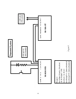
an SX1120-RT, connected to an SEQ, should turn on last and off first, the menu items shown
below should be programmed as follows:
Delay C On
5*
Delay C Off
5*
Aux Sync
C
Aux Delay On
10*
Aux Delay Off
0
*These delay times are an example. Set actual times as required for each application.
In the above example, the turn-on delay for bank C is 5 seconds and the turn-on delay for the
SX1120-RT is 10 seconds. Because the aux sync is set to bank C, the same internal trigger is
used to start both time delays. What then happens is that after bank B turns on, there is a 5
second delay before bank C turns on, then there is further 5 second delay before the SX1120-RT
turns on (the 10 second timer started at the same time as the 5 second timer for bank C). When it
is time to power down, the SX1120-RT turns off immediately (the delay is set to zero), then 5
seconds later bank C turns off.
In another example, if the SX1120-RT should turn on first and off last, the programming would
be as follows:
Delay A On
5*
Delay A Off
5*
Aux Sync
A
Aux Delay On
0
Aux Delay Off
10*
*These delay times are an example. Set actual times as required for each application.
As can be seen in the above two examples, by choosing the appropriate sync setting and delay
times it is possible to position the 4
th
bank anywhere in the sequence.
If an over-ride is used with an expanded system do not use the Special Delay as the 4
th
bank may
not turn on and off in the correct sequence during an over-ride condition.
6.4
Ganged System
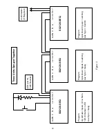
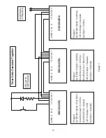
A ganged system consists of two or more SEQs connected together in such a way that they all
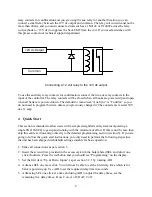
turn off and on together. Figure 4 shows how to connect and program each unit in a three-unit
system. If only two units are to be ganged together then ignore the middle unit in the diagram. If
more than three units are to be ganged together then keep the first and last units set up as shown,

