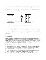
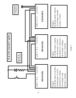
21
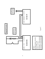
Expanded S
ystem
A-
ON C B
A
1
2 3
4 5
6
7
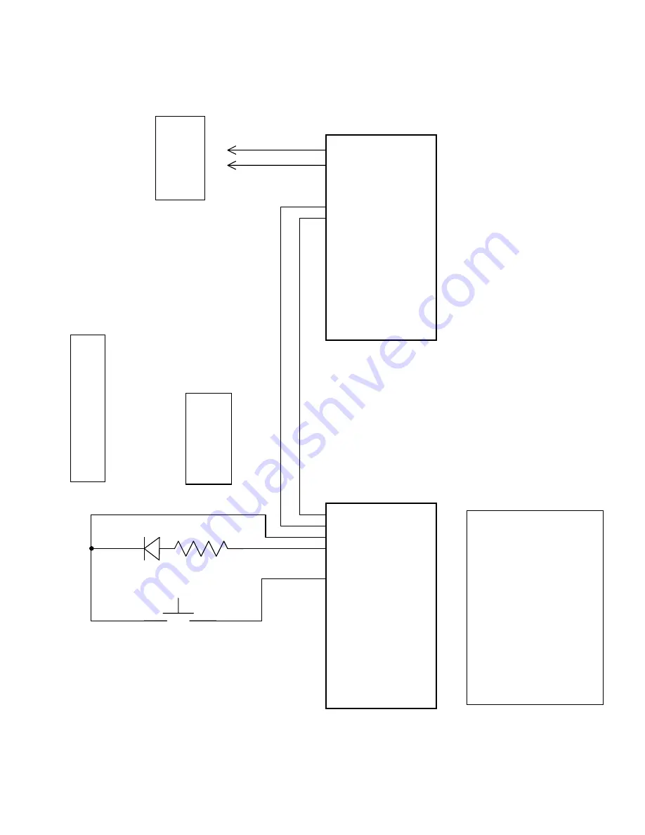
SX2120-SE
Q
A-
On
Sw
itched 1
2 3
4
5 6
7
SX1120-RT
LED
an
d 1
K
,
1/4
W
Resistor
Co
nf
irm
atio
n
(If
Re
qu
ire
d
)
Pr
og
ra
m:
Up & Dow
n
Inp
u
ts =
On
e M
om.
12v
dc Out
put
=
LED
Aux
Sy
nc =
A, B or
C
Aux
Delay
On =
[Set
as Nee
d
ed
]
Aux
D
e
la
y Off
=
[S
et
as N
eede
d]
Figure 3


