background image

 18


1. The unit has a 5-minute delay on start-up 

before beginning normal operation.  Before 

troubleshooting, ensure that 5 minutes have 

passed.

2. Check the temperature set-points of the 

controller to verify that the desired settings are 

still in place.  The factory differential temperature 

should be 3 degrees, and shouldn’t be changed.  

For example, with the factory set differential 

temperature setting of 3 degrees, and a desired 

temperature setting of 45°F (8°C), the unit will not 

start until the water reaches 48°F (9°C).  

4. Check to make sure the controller is set to C1.

5. 

QUALIFIED SERVICE PERSONNEL ONLY: 

Check 

voltage at relay (space terminals on each side), 

which should be 24VAC while the temperature 

controller is calling for cooling, then check for a 

loose wire on the controller.  If none are found, 

check for power at the relay inside the controller.  

If you have power there the other cause would 

be a tripped high/low pressure sensor, in which 

case an HVAC technician will need to service 

your unit.  He/she should check the refrigeration 

pressures with a gauge set to verify that there is 

not a problem with system pressures.  If no 

problems are found with pressure, then the high/

low pressure sensor may need to be replaced.

6. 

QUALIFIED SERVICE PERSONNEL ONLY: 

Check 

the voltage across the ENDS of the main relay 

with a meter.  This should be 240VAC on each 

side when the temperature controller is 

Troubleshooting

This unit is equipped with safety sensors that may 

include high and low pressure sensors for the 

refrigeration circuit and also a flow switch to help 

prevent freezing if there is a pump failure or other 

loss of flow.  If any of these sensors are not 

satisfied, they will not allow the chiller to function.  

Some of the troubleshooting steps listed below 

can be performed by the end user, and some 

of these steps must be performed by a licensed 

HVAC technician.  Retain this guide should your 

chiller ever require servicing in the future.  

Temperature controller has 

no power

1. Check and make sure switch is in the on 

position.

2. Check breaker for proper function.

3. Check flow meter for adequate water flow 

(2.5 GPM per ton).  Insufficient flow will cause 

loss of power.

4. 

QUALIFIED SERVICE PERSONNEL ONLY:


Check 

flow for proper voltage at the unit with an 

electric volt-meter.

5. Visually check for any loose wires.

6. 

QUALIFIED SERVICE PERSONNEL ONLY:


Remove the front cover of the temperature 

sensor and check voltage.  If 24 VAC is 

present, and all wires are installed and tight, 

then most likely the controller will need to be 

replaced.  If no voltage is present, see the next 

step.

7. The controller is wired so that it will not come 

on if there is not sufficient water flow to the unit.  

If there is no voltage at the controller, check 

the flow and verify that the chiller is receiving at 

least 2.5 GPM for each ton of cooling required.  

If there is sufficient flow, see the next step.

8. Check connections of the flow sensor (the 

flow sensor is installed in the water line) to make 

Temperature controller 

is on, but the unit will not 

start

sure you are getting 24VAC across the sensor 

while sufficient water is flowing.  If there is no 

voltage across the sensor leads with a 

proper flow-rate, then the sensor needs to be 

replaced.

9. Check the direction of flow in the water circuit.  

If water is flowing backwards, the flow switch will 

not allow power to the temperature controller, 

and the unit will not function properly.

Summary of Contents for 120-3

Page 1: ...Surna Commercial Chiller Operating Maintenance Manual www surna com 303 993 5271 Models 24 1 42 1 60 1 90 3 120 3 Revised February 2015 ...

Page 2: ......

Page 3: ...iller Safety Guide 6 Parts List 8 Installation Instructions 9 Location 9 Electrical 9 Plumbing 9 Plumbing Tips 10 Operations Instructions 12 Temperature Settings 12 System Maintenance Instructions 12 and Recommendations System Specifications 14 Troubleshooting 18 Temperature Controller has no 18 Power Temperature controller is on but 18 the Chiller Won t Start Fan Turns on and off Even Though 19 t...

Page 4: ...abor Choice of repair facility and technician is at the discretion of the chiller s owner although Surna is happy to assist with locating a technician Note Extended warranty for parts labor and shipping are available for purchase for a nominal fee Contact Surna within 15 days of your chiller s arrival if you would like to purchase an extended warranty Limitation of Liability To the extent allowabl...

Page 5: ... such guarantee Service under warranty is provided only upon presentation of reasonable evidence purchase receipt that the date of claim is within the warranty period Service NOT Under Warranty The warranty is not valid if the defect is due to accidental damage misuse shipping damage neglect or in the case of alterations or repair carried out by unauthorized persons Surna can at its discretion ass...

Page 6: ...ent be sure to inspect the area for water spills which may present a shock hazard to the user Take extra care to mount accessory electrical equipment away from areas regularly exposed to water and be sure to provide secure wire and cable routing to protect personnel from shock hazards Only operate the equipment with an appropriately sized breaker in place and wire sizes with adequate current carry...

Page 7: ...the indoor temperatures are greater than 100 F 38 C the room does not have adequate ventilation DO NOT operate the Surna Chiller without adequate water flow These chiller systems require 2 5 GPM Gallons per Minute per ton of cooling to prevent freezing of the evaporator DO NOT remove the grounded connection while power is being supplied to the Surna Chiller equipment Doing so presents an electric ...

Page 8: ...ist of all parts provided with each Surna Chiller system Surna Chiller Parts List 1 Surna Chiller Product Manual 2 Chiller Unit 3 Strainer 4 Flow Meter 3 Brass Strainer 4 Flow Meter front and side view 2 Chiller Unit ...

Page 9: ... power connections is a product of the chiller unit s ampacity and the length of wire needed Consult an electrician for more information on power wire sizing and connection Installation Instructions Location Electrical IMPORTANT You must use a mixture of Propylene Glycol and water in your reservoir Your reservoir should contain 30 Propylene Glycol to 70 water minimum and contain up to 50 Propylene...

Page 10: ...h PVC glue or PVC fitting In either case we recommend using piping tubing that is sized 1 size larger that the chiller water connections provided Important Plumbing Tips Your chiller requires a flow rate of 2 5 GPM ton i e 5 GPM for a 2 ton chiller 25 GPM for a 10 ton chiller etc Failure to ensure adequate water flow through the chiller may result in system degradation damage to the evaporator and...

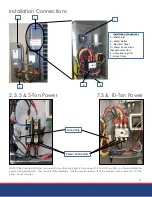
Page 11: ...D E F Installation Connections NOTE If the compressor makes an unusual noise after applying 3 Phase power 7 5 and 10 ton units you have installed the power wiring backwards Shut the unit off immediately shut the electric supply off at the breaker and reverse any 2 of the 3 line conductor wires Power Connectors Grounding 2 3 5 5 Ton Power 7 5 10 Ton Power ...

Page 12: ...ure at 65 F 18 C and adjust up or down based on cooling needs NEVER set this temperature below 45 F 7 C ALWAYS maintain a clean condensing coil for maximum efficiency Chiller units located indoors will need to be cleaned often due to dust build up Units located outdoors are often washed by rainfall ALWAYS maintain 24 of clearance on all sides of the unit and an unobstructed clearance on the top of...

Page 13: ...be to carry sufficient amperage when the compressor starts Damage caused by improper wiring is not covered under warranty Please consult with a qualified electrician for more information on proper breaker and wire sizing if you are not sure Chillers must be installed on concrete or an A C condenser pad Failure to do so can cause the condenser to become dirty sooner from splashing dirt and debris w...

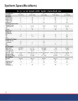
Page 14: ...14 System Specifications ...

Page 15: ...ure Controller D Thermal Expansion Valve E Flow Switch F Low Pressure Switch G Fan Cycle Switch High Pressure Switch located inside unit A C D G E F B Control Panel Components A Control Panel Exterior B Heat Exchanger C Temperature Controller D Thermal Expansion Valve E High Pressure Switch F Low Pressure Switch G Fan Cycle Switch H Flow Switch behind E A C D G E F B H ...

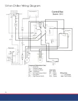
Page 16: ...16 10 ton Chiller Wiring Diagram ...

Page 17: ...2 7 5 ton Chiller Wiring Diagram ...

Page 18: ...re or other loss of flow If any of these sensors are not satisfied they will not allow the chiller to function Some of the troubleshooting steps listed below can be performed by the end user and some of these steps must be performed by a licensed HVAC technician Retain this guide should your chiller ever require servicing in the future Temperature controller has no power 1 Check and make sure swit...

Page 19: ...ese troubleshooting steps have been attempted there could be a problem with one of those components and they may need to be replaced The fan motor is simple to replace and can be done by the end user after all power has been disconnected from the unit If compressor replacement is required a licensed refrigeration technician must complete the associated repairs 9 QUALIFIED SERVICE PERSONNEL ONLY If...

Page 20: ...303 993 5271 info surna com surna com 1780 55th Street Suite A Boulder CO 80301 ...

Reviews: