70ZX416241E-11
11/14
Wiring
Observe these precautions to connect the leads correctly.
※
Black, Blue and F.G leads are connected each other within the circuit.
<Power Supply Connecting>
Connect to a DC24V power supply. To obtain the specified accuracy, warm up your flowmeter for at least
20 minutes.
<Analog Output>
Connect a load resistance between 4 ~ 20mA Output (+) and 4 ~ 20mA Output (-).
The value of load resistance of 500
Ω
or less.
<Pulse Output>
The pulse output is a NPN open collector output. Connect a load resistance between pulse output (+) and
power supply (DC24V). Below are examples of load resistance.
e.g.) Load resistance 1k
Ω
1W
10k
Ω
1/4W
Never do wiring work when power supply is on. Doing so may cause electrical shock.
Refrain from excessive pulling or bending of the cables. Doing so may cause disconnections
which may cause electrical shock and fire hazards.
Make sure to connect all leads correctly. Failure to do so may cause the product to fail.
Apply the voltage in the specified range. Overvoltage may result in smoking or fire.
Do not apply the voltage and current above the capacity to the pulse output (open collector
output). Damages may occur.
CAUTION
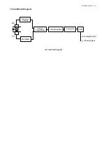
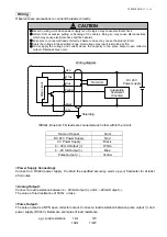
Wiring diagram
Shielding
F.G
Black
Yellow
Blue
White
Red
Main circuit
Recorder
Integrating
flowmeter
(Counter)
DC 24 V
Power supply
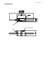
Name of Signal
Color
DC 24 V Power Supply
Red
0 V Power Supply
Black
4 ~ 20 mA Output (+)
White
4 ~ 20 mA Output (-)
Blue
Pulse Output (+)
Yellow


