If you prefer to use the spring adjustment
method, you will need to remove each knife,
remove the jack screws, leave the two springs
under each knife and replace the knife. Follow
the steps below if using the spring adjustment
method.
WARNING: MAKE CERTAIN THAT THE SAW
IS DISCONNECTED FROM THE POWER SOURCE.
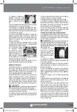
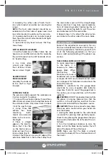
1. Move the hinged
dust port and upper
cover assembly to ex-
pose the cutterhead
(fig.12).
2. Remove the belt guard. Turn the cutterhead
(using the pulley) until the first knife is top
dead center.
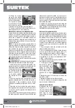
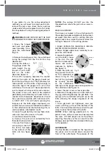
3. Using the knife set-
ting gauge, check the
knife height. The jig
should sit with both
feet on the cutter-
head. See figure 13.
If the knife is properly adjusted, the contact
point at the center of the gauge should just
touch the tip of the knife. If the knife does not
make contact, or if the knife is high enough to
cause the legs of the gauge no to set on the
cutterhead, the knives will need adjusted. Be
sure to inspect all 4 knives in the same manner.
The planer knives will need to be adjusted
periodically and ultimately will need to be re-
moved to be sharpened. Adjustments should
be as precise as possible with tolerance with-
in .0002”-.003”. This will help to prolong the
sharpness of the knife edges. Improperly ad-
justed knives can cause an imbalance condition
in the cutterhead and shorten bearing life, as
well as produce substandard results.
4. Loosen the gib bolts by turning them clock-
wise until the knife is loose in the slot.
5. Carefully remove the knife.
6. Unscrew the jack screws completely from
threaded hole and remove.
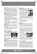
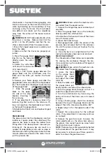
7. Be sure that there is
one spring in each of
the of the two holes
in the bottom of the
knife slot. See figure
14.
NOTICE: The springs DO NOT go into the
threaded hole where the jack screws were in-
stalled.
KNIFE ADJUSTMENT
The knives are locked in the cutterhead with
the wedge type gibs and gib bolts Spring locat-
ed under the knives assist in setting the knife
height. Jack screws under the knives allow fine
tuning to help out in the setting process.
1. MAKE CERTAIN THE MACHINE IS DISCON-
NECTED FROM THE POWER SOURCE.
2. Move hinged upper cover assembly to ex-
pose the cutterhead.
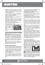
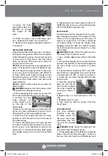
3. Loosen the gib bolts
until the knife is loose
in the slot. The gib
bolts turn clockwise to
loosen and counter-
clockwise to tighten.
See figure 15.
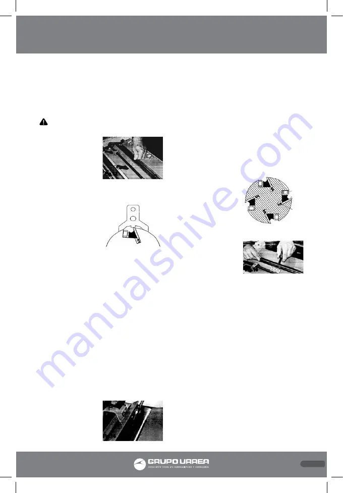
4. Place the knife set-
ting jig over the knife
on the cutterhead as
shown in Fig 16. The
feet of the jig should
be securely planted
on the cutterhead,
making sure the gauge rod remains parallel to
the cutterhead. See figure 16.
5. Lower the jack screws as low as possible.
6. Maintain a steady pressure on the knife set-
ting jig while retightening the gib bolts. The
springs in the cutterhead will push up on the
knife allowing for proper alignment of the
knives.
7. Once gib bolts are tightened, raise jack
screws until they just touch the bottom of the
knife. You should feel resistance when the jack
screw touches the bottom of the knife.
NOTICE: When making adjustments to the
planer knives, all four knives must be adjusted
the same. DO NOT adjust one knife without
adjusting the others as this can result in knife
damage, poor performance and possible injury
to the operator.
CHIP BREAKER
The chip breaker is located on the top side of
the planer and it extends down around the
front of the cutterhead. The purpose of the
27
E N G L I S H •
User's manual
Fig.14
Fig.16
Fig.15
Gib bolt
Knife
Spring
Fig.12
Fig.13
CE716-CE720 manual.indd 27
29/06/15 16:30

