to gauge the distance between the chip deflec-
tor and the knives.
CAUTION: If the chip deflector is set too close
to the knives, the rotating cutterhead may pull
it in and destroy it.
2. If adjustment is necessary, loosen the three
deflector mounting bolts.
3. Make sure the beveled edge of the deflector
faces the cutterhead.
4. Move the deflector until the edge is approxi-
mately 1/8-1/4 from the edge of the knives.
5. Push down on the deflector with a wooden
stick and spin the cutterhead by hand to en-
sure that it does not contact the knives.
CAUTION: Planer knives are extremely sharp.
Please use extra caution when your hands are
near the blades.
6. Retighten the chip deflector mounting bolts
and remount the upper cover and dust port to
the planer.
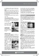
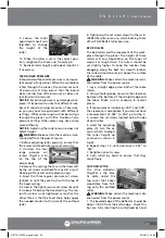
ANTI-KICKBACK FINGERS
Anti-kickback fingers
(Fig.24a) are an added
safety feature on this
planer. They are sus-
pended from a rod
that hangs across the
front of the cutterhead casting. These fingers
should be inspected regularly, ensuring that
they swing freely and easily.
WARNING: DO NOT apply any oil or other
lubricant to the antikickback fingers as this can
attract dust and restrict the free movement of
the fingers. This could result in damage to the
planer, the workpiece, or even serious injury to
the operator or others in the work area.
DO NOT attempt to use the planer if the anti-
kickback fingers are not functioning properly.
PULLEYS
WARNING: Make certain the machine is dis-
connected from the power source.
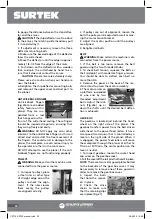
1. To inspect pulleys, place
a steel ruler or other type
of straight edge across the
pulleys to check the align-
ment. If the ruler crosses
them evenly, the pulleys
are aligned correctly.
a
Fig.24
Fig.25
2. If pulleys are out of alignment, loosen the
bolts the pulley can be adjusted as wall as mov-
ing the motor mount bracket.
3. Adjust the motor position until the pulleys
are aligned.
4. Retighten all bolts.
BELTS
WARNING: Make certain the machine is dis-
connected from the power source.
1. If the belt is too loose, remove the belt
guard using the two threaded knobs.
2. To check belt tension, squeeze the Belts at
their midpoint with moderate finger pressure.
You should be able to deflect each belt no
more than 3/4.
3. Remove the panel at the back of the ma-
chine stand to access the motor assembly.
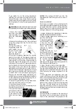
4. The motor pivots on
a platform suspended
at one end by two
threaded adjustment
bolts. Adjust the lock-
nuts (Fig.26a) up or
down the shafts until the desired belt deflec-
tion is achieved.
GEAR BOX
The gearbox is located just behind the hand-
wheel on the right side of the planer. The
gearbox transfers power from the belt driven
cutterhead to the power feed rollers. It has a
two speed transmission that is controlled by a
lever on the right side of the planer. When it
is engaged, the power feed rollers will move
the workpiece through the planer at either 16
ft/ min or 30 ft/min. The center position on the
lever is neutral.
1. To inspect gearbox, loosen the socket head
cap screw on the gearbox cover.
2. Pull the cover off the roll pins that hold it in place.
NOTE: There are two metal guard plates bolted
to the backside of the gear box cover. It may
be necessary to remove one of these guards in
order to remove the gear box cover.
3. Inspect the bolts
that hold the sprock-
ets in place.
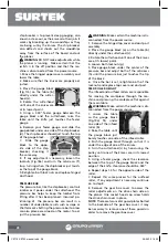
4. Check the drive
chains to make sure
that the retaining clips
are in place (Fig.27).
Fig.27
Fig.26
a
b
30
CE716-CE720 manual.indd 30
29/06/15 16:30

