background image

13

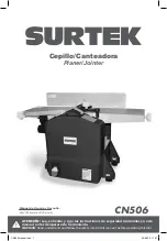
1. FENCE.
2. WORKING TABLE.
3. SAFETY SWITCH.
4. AIR DUST EXTRACTOR DEVICE.

ASSEMBLY

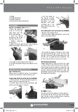
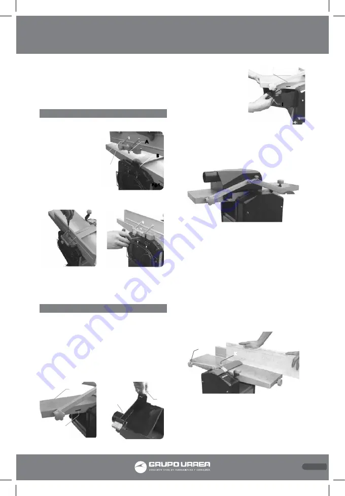
ADJUST THE RIPPING FENCE (Fig. 1)
•  Place  the  clamping 
screw ‘A’ of the rip-
ping fence into the 
slot of the sidewall.
•  Lock  by  lateral 
shifting of the fence 
towards the screw ‘B’. 
•  Tighten  clamping 
screw, Fig. 2.
• Adjust the fence parallel with the surfacing 
tables and tighten the screw ‘B’, Fig. 3.

• For angle setting, release the knob ‘C’.
• A precise manual setting can be done on the 
scale ‘D’.

OPERATION INSTRUCTIONS

DUST EXTRACTION
When used in enclosed rooms, the machine 
must be connected to a dust extractor unit. 

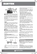
Connecting the dust extractor for PLANING

• Lift the arm ‘G’ of the cutter block guard in 
order to free the mortises (Fig. 4).
• On both sides of the suction connector, pull 
out the switching pins ‘I’ (Fig. 5).

•  Set  the  table  to 
the lowest position 
and push the suction 
connector into the 
machine until both 
switching pins I can 
slide into the mortises 
‘H’ (Fig. 6).

Connecting the dust extractor for JOINTER

• Remove the ripping fence.
• Push the cutter block guard back and fix the 
suction connector (Fig.7).

• The suction connector is fitted in such a way 
that both switching pins are in line with the 
mortises. Then push the switching pins into the 
mortises. For an optimum dust extraction, the 
air flow rate must be 20 m/s at a minimum.

CUTTER BLOCK GUARD

Height adjustment is done with the star grip 
‘J’ screw fitted to the left side of the machine. 
After releasing the star grip screw (Fig.8-K), the 
cutter block guard can be moved to the side 
and the correct planing width set. Press the 
guard down again to fix it in the right position, 
and tighten the handles.

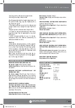
PLANING 

(Fig.9)

The amount of chip removal is set by means ‘L’ 
of the scale ‘M’ on the front side of the table-
top. The best surface is obtained at a planing 
depth between 0.5 and 1.5 mm. 

Fig.7

Fig.4

G

H

Fig.6

I

H

Fig.5

I

F

Fig.8

J

K

A

B

C

D

Fig.1

Fig.2

Fig.3

E N G L I S H •

User's manual

CN506 manual.indd   13

23/06/15   17:07

Summary of Contents for CN506

Page 1: ...r s Manual and Warranty ATENCI N Lea entienda y siga las instrucciones de seguridad contenidas en este manual antes de operar esta herramienta WARNING Read understand and follow the safety rules in th...

Page 2: ...cuidados de las herramientas el ctricas Advertencias de seguridad para cepillo canteadora Caracter sticas Ensamble Instrucciones de operaci n Mantenimiento Solucionador de problemas Especificaciones t...

Page 3: ...edad El agua que entre en la herramienta aumentar el riesgo de choque el ctrico No abuse del cable No usar nunca el cable para llevar levantar o desenchufar la herramienta el ctrica Mantenga el cable...

Page 4: ...onsable de su segu ridad Los ni os deben supervisarse para ase gurar que ellos no empleen los aparatos como juguete UTILIZACI N Y CUIDADOS DE LAS HERRAMIENTAS EL CTRICAS No fuerce la herramienta el ct...

Page 5: ...res de aceite y grasa Antes de encender la m quina compruebe que se han retirado las llaves y herramientas para hacer ajustes No utilice la m quina bajo la lluvia o en con diciones de humedad Utilice...

Page 6: ...protecci n personal como lentes de se guridad y cubrebocas Instale un extractor de polvo Pueden ocurrir accidentes debido a cuchillas da adas o desgastadas Verifique el estado de las cuchillas peri di...

Page 7: ...a m quina Despu s de aflojar la perilla Fig 8 K la guarda se puede deslizar a un lado y se puede ajustar la anchura de lo que va a cepi llar Presione la guarda en la posici n correcta y ajuste de nuev...

Page 8: ...eben de estar ajustados a un torque de 8 4 Nm RECUERDE Las cuchillas del cepillo canteadora garantizan un corte limpio el cual hace traba jar menos el motor Despu s de tres acciones de corte una remo...

Page 9: ...limentaci n Las cuchillas no tienen filo Cambie las cuchi llas Alimentaci n irregular Aplique una presi n constante y reduzca la velocidad de alimenta ci n CUANDO EST REALIZANDO CORTES DE CAN TEADO EL...

Page 10: ...ace damaged cords immediately The use of damaged cords can shock burn or electric shock If an extension cord is necessary a cord with adequate size conductors should be used to prevent excessive volta...

Page 11: ...clean Cut ting tools in good condition with sharpened edges are less likely to stuck in workpieces or easier to control Is recommendable to use a safety device suit able such a thermal and diferential...

Page 12: ...table top require the use of a table length ex tension or a roller stand optional equipment When used in enclosed rooms the machine must be connected to a dust extractor unit to remove wood chips and...

Page 13: ...ntil both switching pins I can slide into the mortises H Fig 6 Connecting the dust extractor for JOINTER Remove the ripping fence Push the cutter block guard back and x the suction connector Fig 7 The...

Page 14: ...he knife is done Place the knife support onto the knife Slightly tighten the four clamping bolts Repeat these actions for the second knife Then adjust the planer jointer knives exactly with the output...

Page 15: ...ction the machine does not restart automatically Upon return of the voltage the machine must be switched on again MACHINE STOPS DURING PLANING Overload protection reacts due to blunt kni ves infeed to...

Page 16: ...fied by unauthorized or unqualified person Urrea Herramientas Profesionales S A de C V garantiza este producto por el termino de 1 a o en sus piezas componentes y mano de obra con tra cualquier defect...

Reviews: