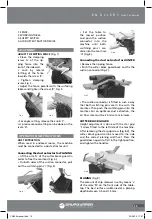
14
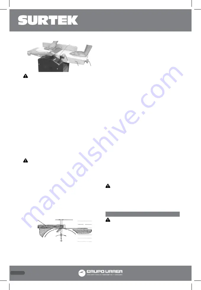
WARNING: The guard must cover the part
of the cutter block not used. Working position
is in front of the machine at the side of the
infeed table. Put the fingers of both hands on
top of the work piece. Do not hold the work
piece edges.
The work pieces to be planed must lay firmly
on the table so they can be guided safely. For
short work pieces use a feed stick.
JOINTER
• Following the scale and using the handle ‘O’
on the spindle, set the jointer table to the de-
sired height: 1 rotation = 3 mm.
• Narrow wood is introduced in the center.
• When jointing, the table must be treated
with oil at regular intervals. After a long pe-
riod of use, or when planing humid wood, it
can happen that the work piece is not further
pulled in.
WARNING: In case of a defect, switch off
the machine at once. Do not remove any chips
or splinters from the tables while the machine
is running. Work pieces below 250 mm may not
be planed.
CHANGING THE KNIVES
(Fig. 10)
• Put the main switch of the machine to OFF
position.
• Pull the power supply plug from the socket.
• Block the cutter block guard in the lifted
position.
• Release and remove the four knife clamping
screws.
• Lift the knives and knife support from the
cutter block.
• Remove the chips and any resin from the cut-
ter block and knife support.
• Place new knives into the cutter block and
fix them with the rectangle slots in both screw
heads. (With these two screws, height-adjust-
ment of the knife is done.)
• Place the knife support onto the knife.
• Slightly tighten the four clamping bolts.
• Repeat these actions for the second knife.
• Then adjust the planer/jointer knives exactly
with the output table. Use a ruler that you put
onto the output table.
• By the two set screws, the knife can be ad-
justed for height.
• By turning the cutter block and using the
ruler, you can see the height adjustment.
• The knife is exactly set, when the ruler is
moved by the knives not higher than 3 mm.
• After a successful knife setting, all clamping
screws must be tightened (8.4 N/m).
PLEASE MIND: Sharp planer/jointer knives
guarantee a clean planing surface and put less
stress on the motor.
• After three grinding actions, a maximum
material removal of 3 x 0.05 mm may not be
exceeded.
• The planer/jointer blades used on this ma-
chine are not suitable for rebating and dove-
tailing.
• Finally lower the cutter block guard again
onto the table. Cover the cutter block and
block it with the star grip screw.
IMPORTANT: Make sure there is sufficient
space for handling the work piece over the
whole length without the operator (or another
person) having to stand in line with the work
piece.
MAINTENANCE
IMPORTANT: Turn planer/jointer off and
unplug it from the power source when per-
forming maintenance service, changing parts
or removing guards.
Machine care
The planer/jointer requires little maintenance.
The ball bearings are permanently lubricated.
After approx. ten operating hours, lubrication
of the following parts is recommended:
Fig.10
Ruler
2 mm - 3 mm
(5/64”- 1/8”)
max. 1,1 mm
Fig.9
M
O
N
L
CN506 manual.indd 14
23/06/15 17:07

