background image

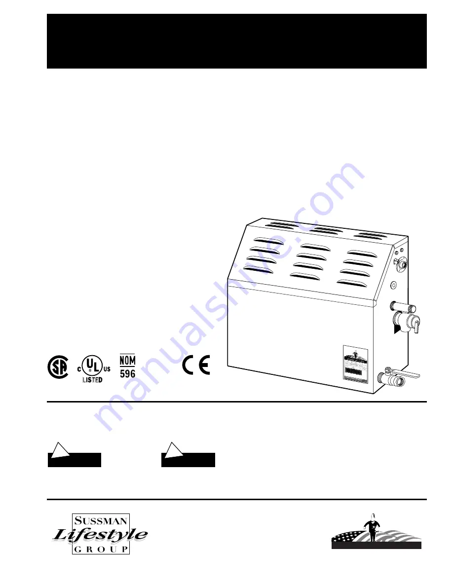
MODELS: 

_________

MS-65

MS-90

MS-150

MS-225

MS-300

MS-400

IMPORTANT NOTE

:

As you follow these instructions, you will notice warning and caution symbols. This blocked information is important for the
safe and efficient installation and operation of this generator.
These are two types of potential hazards that may occur during this installation and operation:

!

WARNING

!

CAUTION

Table of Contents: . . . . . . 

Page

Before Installing . . . . . . . . . . . . . . . . . . . . . 1

Steam Room Requirements . . . . . . . . . . . . 1

Locating the Steam Generator Unit . . . . . . 2

Typical Installation . . . . . . . . . . . . . . . . . . . 2

MS Super 4, 5, 6 Typical Installation. . . . . . 3

Installation . . . . . . . . . . . . . . . . . . . . . . . . . 4

Plumbing
Water Supply

Generator Dimensions . . . . . . . . . . . . . . . . 5

Electrical Specifications . . . . . . . . . . . . . . . 6

Input Power Wiring . . . . . . . . . . . . . . . . . . 7

Wiring Diagrams . . . . . . . . . . . . . . . . . . 8- 10

Optional Autoflush Feature . . . . . . . . . . . 11

Check Out & Operation . . . . . . . . . . . . . . 12

Major Electrical Systems Test . . . . . . . . . . 12

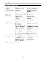
Trouble Shooting . . . . . . . . . . . . . . . . 13- 15

Five Easy Steps to Properly Size . . . . . . . . 16

Replacement Parts Diagram . . . . . . . . . . . 17

Replacement Parts List . . . . . . . . . . . . . . . 18

Warranty . . . . . . . . . . . . . . . . . . . . . . . . . 19

states a hazard may cause serious
injury or death if precautions are
not followed.

signals a situation where minor
injury or product damage may occur
if you do not follow instructions.

IMPORTANT NOTE

:

This highlights information that is especially
relevant to a problem-free installation.

MrSteam

PUR 101289    Rev. 4/01

MrSteam

®

Residential Steambath Generator Systems

Installation,Operation & Maintenance Manual

A Division of Sussman-Automatic Corporation

43-20 34th Street, Long Island City, NY 11101 • (718) 937-4500 
1-800-767- 8326  • Fax: (718) 472-3256 • www.mrsteam.com

Western Regional Offices

9410 S. La Cienega Blvd., Inglewood CA 90301
1-800 72 STEAM (1-800 727-8326) • Fax: (310) 216-2944

Steam Outlet

Steam Head

Made in USA

Listed Steam Bath

Generator 777D

ANSI

Drain

Safety Valve

MS-SUPER 1

MS-SUPER 2

MS-SUPER 3

MS-Super 4

MS-Super 5

MS-Super 6

MODEL____________  Serial No._________________

Summary of Contents for MrSteam MS-Super 1

Page 1: ...5 Five Easy Steps to Properly Size 16 Replacement Parts Diagram 17 Replacement Parts List 18 Warranty 19 states a hazard may cause serious injury or death if precautions are not followed signals a situation where minor injury or product damage may occur if you do not follow instructions IMPORTANT NOTE This highlights information that is especially relevant to a problem free installation MrSteam PU...

Page 2: ...on IMPORTANT MR STEAM units are intended to be operated with a MR STEAM timer and or temperature control only and are to be installed strictly in accordance with the specific instructions supplied with these optional accessories and the information contained in this manual Mr Steam steam generators are connected to 240V line voltage and contain live electrical components All instal lation and serv...

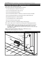
Page 3: ...as required 9 Provide access to both ends of steambath generator for servicing See page 5 10 Steam line safety valve and drain valve become hot during operation Provide appropriate protection 11 MR STEAM CONTROLS can be located inside the steam room or on the outside of the steam room See separate CONTROL INSTALLATION AND OPERATION INSTRUCTIONS for specific details If the SMART TWO or SMART PLUS c...

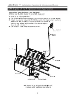
Page 4: ...tions for Models MS Super 4 MS Super 5 and MS Super 6 1 Install each unit as in a single installation 2 Connect the SMART PLUS control to either unit per instructions supplied with the SMART PLUS control 3 Using the interconnecting cable provided PN 103608 connect the Black plug to the Liquid Level Control Board Terminal marked TANDEM in the same unit connected to the SMART PLUS control Connect th...

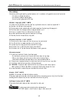
Page 5: ...ing of condensate 5 Pitch steam line 1 4 per foot towards steam head or steam generator Steam Head 1 Locate steam head 6 to 12 inches from floor except For tub shower enclosures install steam head 6 inches above tub top ledge When used in shower stall with acrylic or other non heat resistant floors install steam head 20 30 inches from floor or use a steam shield MS 103412 2 If steam room is provid...

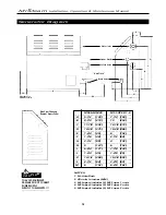
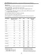
Page 6: ..._____________________________________ I 6 3 4 171 7 7 8 200 _______________________________________ J 1 3 4 45 1 3 8 35 _______________________________________ K 14 1 2 368 19 3 4 502 _______________________________________ L 2 1 2 64 2 3 8 60 _______________________________________ M 6 152 6 3 8 162 Generator Diagram 5 NOTES 1 M AutoFlush 2 All units in inches MM 3 MS Super4 includes 2 MS Super 1...

Page 7: ..._____________________________________________________ MS 225 250 7 5 208 36 8 240 32 8 _______________________________________________________________________ MS 300 325 8 5 208 41 8 240 36 8 _______________________________________________________________________ MS 400 375 9 0 208 44 8 240 38 8 _______________________________________________________________________ MS Super 1 475 10 0 208 49 8 24...

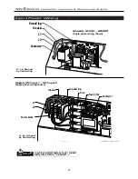
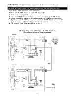
Page 8: ...g L2 L1 Ground Models MS65 MS400 single phase wiring shown L1 L2 Ground by field wiring L1 L2 Ground by field wiring Models MS Super 1 MS Super 6 single phase wiring shown _________________________________________________ TO AVOID EQUIPMENT DAMAGE DO NOT CONNECT POWER SUPPLY DIRECTLY TO ELEMENTS _________________________________________________ CAUTION ...

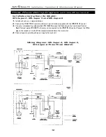
Page 9: ...Operation Maintenance Manual 8 Wiring Diagrams Single Phase MS Super 1 MS Super 2 MS Super 3 Three Phase MS 65 MS 90 MS 150 MS 225 MS 300 MS 400 MS Super 1 MS Super 2 MS Super 3 Single Phase MS 65 MS 90 MS 150 MS 300 MS 400 ...

Page 10: ...N 103608 connect the Black plug to the Liquid Level Control Board Terminal marked TANDEM in the same unit connected to the SMART PLUS control Connect the White plug to the second unit to the White receptacle located above the water inlet 4 Connect separate plumbing and power supplies for each unit Single Phase Wiring Diagram with Smart Plus control MrSteam Installation Operation Maintenance Manual...

Page 11: ... unit per instructions supplied with the SMART PLUS control 3 Using the interconnecting cable provided PN 103608 connect the Black plug to the Liquid Level Control Board Terminal marked TANDEM in the same unit connected to the SMART PLUS control Connect the White plug to the second unit to the White receptacle located above the water inlet 4 Connect separate plumbing and power supplies for each un...

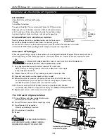
Page 12: ...le provided connect AutoFlush valve end B to ball valve NOTE If there is not enough room for the valve an elbow and a short nipple not provided can be added 2 Connect valve end A and B are indicated on bottom of AutoFlushValve 3 Open ball valve handle must be aligned with brass nipple 4 Remove knock out in jacket and connect cord Connect cord to FLUSH terminals on the liquid level control circuit ...

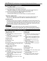
Page 13: ... is recommended for generator longevity Check Out and Operation WARNING Transformer Test 1 Power to unit is on 2 Check voltage at blue and white terminals of the PC board 24VAC 3 If voltage is zeroVAC replace transformer If voltage is less than 24VAC check incoming power Control Test 1 Power to unit is on 2 Transformer test is good 3 Turn control on 4 Check voltage at yellow white terminals of the...

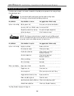
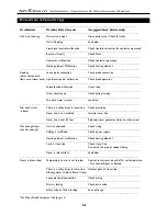
Page 14: ..._____________________________________________ System is not working Improper installation Review instructions _______________________________________________________ Incorrect power supply Check power supply _______________________________________________________ Transformer malfunction Check transformer output Replace if necessary _______________________________________________________ Control is...

Page 15: ...steam line Check plumbing _________________________________________________________ Steam line is not insulated Insulate steam line _________________________________________________________ Steam line is over 50 feet Relocate steam generator closer to steam room _________________________________________________________________________ Not enough steam Unit is undersized Check sizing ______________...

Page 16: ...t Over voltage Check voltage ___________________________________________________ Incoming power connected Check connections see page 7 directly to elements ___________________________________________________ Liquid level control malfunction Check probe and contactor operation ___________________________________________________ Probe shorted to ground Check probe circuit ___________________________...

Page 17: ...ruction details Otherwise the manufacturer disclaims responsibility for the sizing of a model selected L W H a b c d e f g h i Model No Kw Maximum Room Available Voltage Amps Volume cu ft 50 60 HZ _____________________________________________________________________ MS65 4 5 65 208V 1PH 22 240V 1PH 19 _____________________________________________________________________ MS90 5 100 208V 1PH 24 240V...

Page 18: ...Power block Power supply knock out Drain line Transformer Liquid level Control board Water feed solenoid Water feed Water feed hose Steam outlet Safety valve Data plate Auto flush valve Stainless steel tank Heating element Access cover Liquid level probe Contactor Control connection Power block Power supply knock out Fuse block Fuse Ground lug MS Super Models MS Super 1 MS Super 6 with Autoflush s...

Page 19: ... phase 29041BMS Heating Element 4 5KW 208V MS 65 29041CMS Heating Element 4 5KW 240V MS 65 29051BMS Heating Element 5 KW 208V MS 90 29051CMS Heating Element 5 KW 240V MS 90 29061BMS Heating Element 6 KW 208V MS 150 29061CMS Heating Element 6 KW 240V MS 150 29071BMS Heating Element 7 5KW 208V MS 225 29071CMS Heating Element 7 5KW 240V MS 225 29081BMS Heating Element 8 5KW 208V MS 300 29081CMS Heati...

Reviews: