Mr
S
team
Installation, Operation & Maintenance Manual
1.
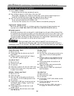
Turn on SMART CONTROL
• Follow specific instruction sheet provided with controls.
2.
Steam will begin to appear in a (5-8) minutes at the steam head.
• When system is equipped with a temperature control, steam will shut off when desired temperature is
reached and will automatically resume when room temperature drops below set point.
3.
Steam will shut off automatically when SMART CONTROL counts down to zero.
• To shut steam off manually, turn off CONTROL “OFF”.
• To clear steam from enclosure area, turn on cold or lukewarm shower before opening door.
Optional Equipment
Refer to specific instruction sheets for installation, operation and maintenance of optional equipment and
accessories such as SMART/ONE, SMART/TWO, SMART/PLUS, SMART/REMOTE, AUTOFLUSH, etc.
Maintenance
MR. STEAM steambath generators are designed for unattended operation and require little maintenance. Other
than periodic draining, maintenance procedures are not required. Every 2 months, or more often in “hard” water
areas, the drain valve should be opened fully flushing out accumulated materials, salts and other particles which
are natural by-products of boiling water. Note: For best results, this should be done immediately after using the
steambath generator, while contents are still hot and with the control off!
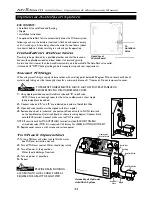
Draining immediately after a steam cycle may expose PVC and other piping to high
temperature water. Check local codes. The unit will refill automatically when the control is
activated again. In areas of very hard water, a MR. STEAM autoflush system is recommended for generator longevity.
Check Out and Operation
!
WARNING
Transformer Test
1.
Power to unit is on.
2.
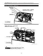
Check voltage at blue and white terminals of the PC
board =24VAC.
3.
If voltage is zero VAC, replace transformer. If voltage is
less than 24VAC, check incoming power.
Control Test
1.
Power to unit is on.
2.
Transformer test is good.
3.
Turn control on.
4.
Check voltage at yellow & white terminals of the PC board.
5.
If voltage is zero VAC, check control wiring and connections
for proper fit and installation.
Water Solenoid Test
1
.
Power to unit is on.
2.
Control test is good.
3.
Drain water from unit by opening manual drain valve
(not necessary if unit has a functioning autoflush valve).
4.
Turn control on.
5.
Check voltage at “PUMP” (grey and white terminals) on
the PC board = 24VAC. If voltage = zero VAC, then
proceed to probe test.
6.
Check voltage at the gray and white wires at water
solenoid = 24VAC.
7.
If voltage is 24VAC, and water does not enter, replace
water solenoid valve.
Major Electrical Systems Test
Probe Test
1.
Turn power off.
2.
Drain water from unit by opening manual drain valve
(not necessary if unit has a functioning autoflush
valve.)
3.
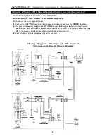
Disconnect purple wire and green/yellow wire from
the Liquid Level Control Board labeled “Probe” and
“GND”.
4.
Check resistance between the purple wire and
green/yellow wire.
5.
With water level low, probe resistance should be
“OPEN”, if not, replace probe.
6.
If probe resistance is “OPEN” then replace Liquid
Level Control board.
Contactor
1.
Power to unit is on.
2.
Water solenoid test is good.
3.
Turn control on.
4.
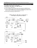
Check voltage at “CONT” (white and blue terminals)
on the PC board.
5.
Check voltage at blue and white wires at the
contactor coil = 24VAC.
6.
If contactor coil voltage is 24VAC and contactor is
not engaging, then contactor must be replace.
12


