Sutron Corporation X-Link Operations & Maintenance Manual, Rev 1.63 5/24/2016 pg. 161
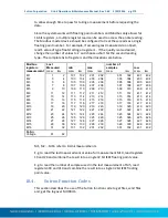
M1 Right Digits
2
M1 Meas Interval
00:01:00
M1 Tx Data Content All Logged
M2 Right Digits
1
M2 Meas Interval
00:05:00
M2 Tx Data Content Last
Tx Time
00:00:30
Tx Interval
00:05:00
D1D~A8@NI@NH@NG@NF@NE@DGF
Pseudobinary
values
Decoded
into
decimal
Completely
decoded
Description
D
Denotes Pseudobinary D format
4
Retransmission
D~
318
Nov 14th
Day of the year of the most recent reading.
For 2014, it is Nov 14th.
A8
120
2:00 AM
Minutes into the day. We can tell that this
transmission should have been made at
02:00 on Nov14th and parse the data
accordingly.
@NI
905
9.05
Sensor M1 collected at 02:00
@NH
904
9.04
Sensor M1 collected at 01:59
@NG
903
9.03
Sensor M1 collected at 01:58
@NF
902
9.02
Sensor M1 collected at 01:57
@NE
901
9.01
Sensor M1 collected at 01:56
@DG
263
26.3
Sensor M2 collected at 02:00
F
12
12.00V
Battery voltage
16.6.
Six Bit Binary Encoded Format
The 6 bit binary format is used to encode numbers into displayable ASCII
characters. Fractional numbers cannot be represented, so, for instance a battery
voltage of 13.04 volts set up with 2 right digits will be sent as 1304.
A 1 byte encoded number can range from -32 to +31.
A 2 byte encoded number can range from -2048 to +2047
A 3 byte encoded number can range from -131072 to +131071
Binary encoded numbers are always sent most significant bytes first. The
number itself is broken down into 6-bit digits, and each digit is placed in one
byte of data. The number 64 (ASCII @) is added to each digit to make it fall
within the range of displayable ASCII characters. The only exception is that 127
(ASCII <DEL>) is sent as 63 (ASCII ?)


