TRIO MPC-145 SERIES MICROMANIPULATOR SYSTEM OPERATION MANUAL – REV. 2.62C (20191001) (FW V2.62)
25
3.3.9
Mode Indications
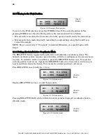
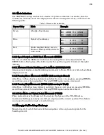
The TRIO MPC-100 system has three modes of operation: Absolute coordinates, Relative
coordinates, and Lock mode. The display turns color for each specific mode, as shown in the
following table.
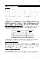
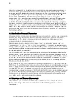
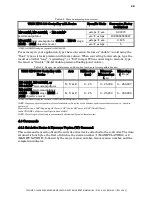
Table 3-2. Screen colors and modes
Screen Color
Mode
Example
Green
Absolute Coordinates
Blue
Relative Coordinates
Red
Knobs disabled during move to
Home or Work position, while in
Lock mode.
3.3.10
Speed Control and ROE Knob Movements (SPEED)
The rate at which the ROE axis knobs move the manipulator can be adjusted with the
SPEED button. Each press of the button cycles through four speeds: 0 (normal) through 3
(fastest).
3.3.11
Movement Knobs Disabling and Lock Mode ([SPEED]/LOCK)
Axis-movement knobs are disabled during movements to Home, Work, or while in Lock Mode
(display is in red).
3.3.12
Pausing Home Movements (HOME (while moving to Home))
After Move to Home has been initiated, and while the move is in progress, pressing HOME a
second time pauses the manipulator. Pressing HOME again resumes movement.
3.3.13
Pausing Work Movements (WORK (while moving to Work))
After Move to Work has been initiated, and while the move is in progress, pressing WORK a
second time pauses the manipulator. Pressing WORK again resumes movement.
3.3.14
Pulse Mode and Virtual D-Axis Movement (PULSE)
Pulse mode advances the D axis in 2.85 µm steps. Each press of the PULSE button
increments the Diagonal axis by one 2.85-µm step beyond the current position. This feature
can be used to penetrate tough or resistant tissue.
3.4
Micropipette/Headstage Exchange
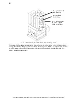
Mounted on the front of the Z-axis of the manipulator is the angle-control plate for the
headstage mount.
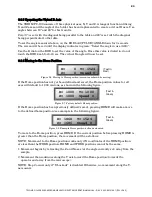
X=- 0 Y= 0
Z= 0 >= 0
X= 1868 Y= 1524
Z= 1686 >= 2706
X= 0 Y= 1524
Z= 0 >= 0

