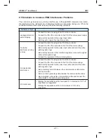
EMC NICE3000
new
User Manual
- 210 -
•
It is recommended that all control cables be shielded.
•
It is recommended that a shielded cable be used as the output power cable of the AC
drive; the cable shield must be well grounded. For devices suffering from interference,
shielded twisted pair (STP) cable is recommended as the lead wire and the cable shield
must be well grounded.
8.4.3 Cabling Requirement
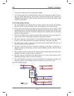
1. The motor cables must be laid far away from other cables, with recommended distance
larger than 0.5 m. The motor cables of several controllers can be laid side by side.
2. It is recommended that the motor cables, power input cables and control cables be laid
in different ducts. To avoid electromagnetic interference caused by rapid change of the
output voltage of the controller, the motor cables and other cables must not be laid side
by side for a long distance.
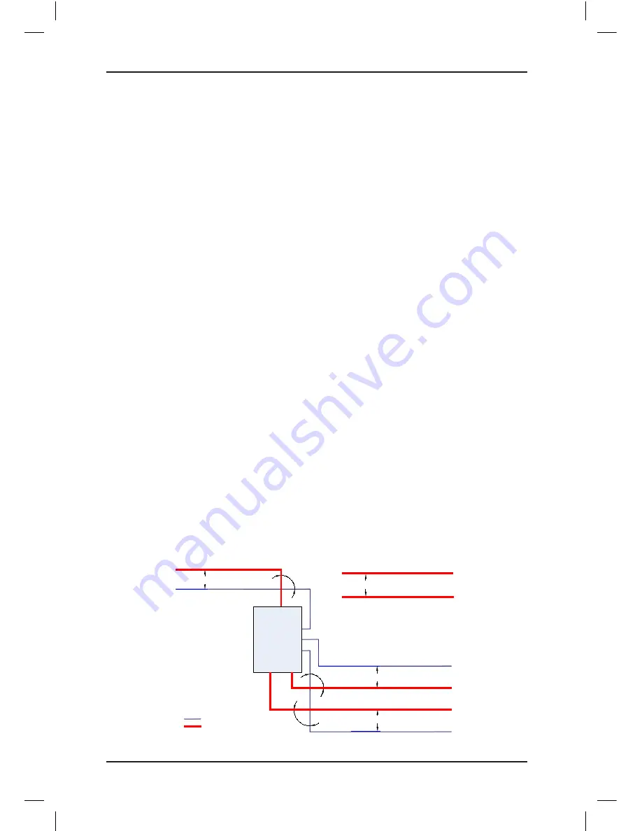
3. If the control cable must run across the power cable, make sure they are arranged at an
angle of close to 90°. Other cables must not run across the controller.
4. The power input and output cables of the controller and weak-current signal cables
(such as control cable) should be laid vertically (if possible) rather than in parallel.
5. The cable ducts must be in good connection and well grounded. Aluminium ducts can
be used to improve electric potential.
6. The filter, controller and motor should be connected to the system (machinery or
appliance) properly, with spraying protection at the installation part and conductive metal
in full contact.
7. The controller must be connected to the cabinet properly, with spraying protection at the
installation part and conductive metal in full contact.
8. The filter must be connected to the cabinet properly, with spraying protection at the
installation part and conductive metal in full contact.
9. The motor should be connected to the system (machinery or appliance) properly, with
spraying protection at the installation part and conductive metal in full contact.
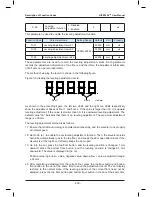
Figure 8-2 Cabling diagram
NICE3000
new
integrated
elevator
controller
Min. 200 mm
Min. 300 mm
Power cable
Motor cable
Min. 500 mm
Min. 500 mm
Braking resistor cable
Motor cable
Power cable
90°
90°
90°
Control cable
Control cable
Power cable
Control cable
Control cable
Summary of Contents for NICE3000 New
Page 1: ......
Page 13: ......
Page 14: ...1 Safety Information and Precautions ...
Page 21: ...Safety Information and Precautions NICE3000new User Manual 20 ...
Page 22: ...2 Product Information ...
Page 33: ...Product Information NICE3000new User Manual 32 ...
Page 34: ...3 Mechanical and Electrical Installation ...
Page 67: ...4 Use of the NICE3000new ...
Page 79: ...5 System Commissioning and Application Example ...
Page 105: ...6 Function Code Table ...
Page 136: ...Function Code Table NICE3000new User Manual 134 ...
Page 137: ...7 Description of Function Codes ...
Page 205: ...8 EMC ...
Page 214: ...EMC NICE3000new User Manual 212 ...
Page 215: ...9 Troubleshooting ...
Page 230: ......
Page 233: ......

