NICE3000
new
User Manual Mechanical and Electrical Installation
- 49 -
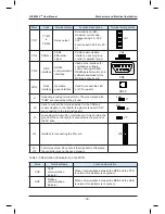
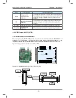
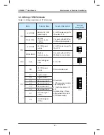
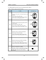
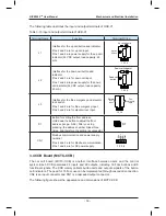
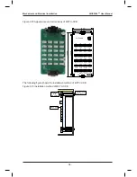
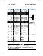
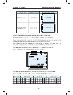
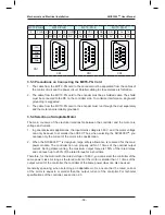
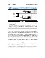
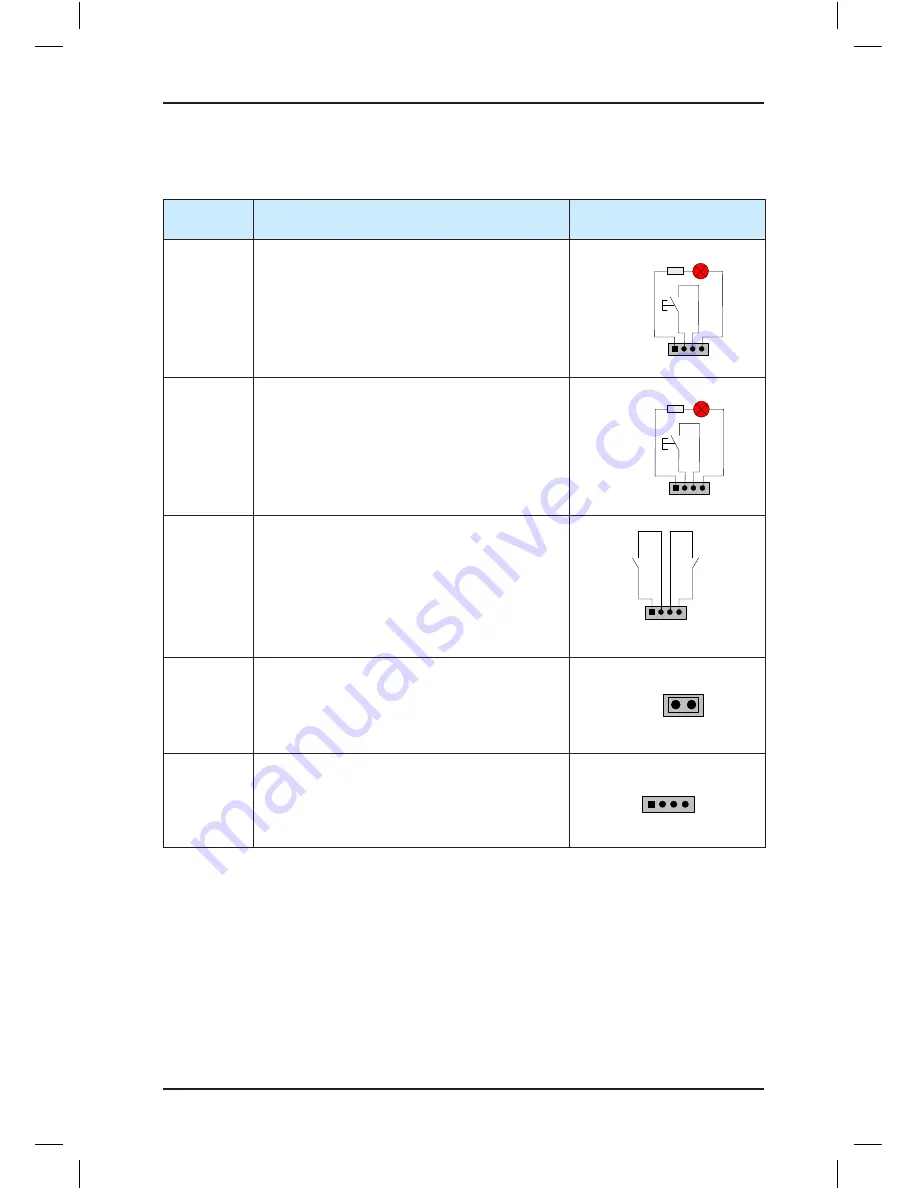
The following table describes the input and output terminals of HCB-D2.
Table 3-8 Input and output terminals of HCB-D2
Terminal
Name
Function
Terminal Wiring
UP
Interface for the up call button and indicator
Pins 2 and 3 are for up call input.
Pins 1 and 4 are power supply for the up call
indicator (24 VDC output, load capacity: 40 mA).
1 2 3 4
Up call indicator
Up call
button
DOWN
Interface for the down call button and indicator
Pins 2 and 3 are for down call input.
Pins 1 and 4 are power supply for the down call
indicator (24 VDC output, load capacity: 40 mA).
1 2 3 4
Down call indicator
Down call
button
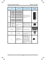
XF/ST
Interface for the fire emergency and elevator
lock switch
Pins 1 and 2 are for fire emergency input.
Pins 3 and 4 are for elevator lock input.
1 2 3 4
Fire
emergency
input
Elevator
lock input
J1
Terminal for setting the floor address
Short J1, and press the UP button or DOWN
button to set the floor address (range 0–56).
After the jumper cap is removed, the address is
automatically stored.
J1
CN1
Modbus communication and power supply
terminal
Pins 2 and 3 are for Modbus communication.
Pins 1 and 4 are for power supply.
1 2 3 4
MOD
-
MOD
+
24
V
COM
Summary of Contents for NICE3000 New
Page 1: ......
Page 13: ......
Page 14: ...1 Safety Information and Precautions ...
Page 21: ...Safety Information and Precautions NICE3000new User Manual 20 ...
Page 22: ...2 Product Information ...
Page 33: ...Product Information NICE3000new User Manual 32 ...
Page 34: ...3 Mechanical and Electrical Installation ...
Page 67: ...4 Use of the NICE3000new ...
Page 79: ...5 System Commissioning and Application Example ...
Page 105: ...6 Function Code Table ...
Page 136: ...Function Code Table NICE3000new User Manual 134 ...
Page 137: ...7 Description of Function Codes ...
Page 205: ...8 EMC ...
Page 214: ...EMC NICE3000new User Manual 212 ...
Page 215: ...9 Troubleshooting ...
Page 230: ......
Page 233: ......


