System Commissioning and Application Example NICE3000
new
User Manual
- 90 -
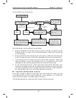
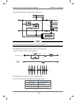
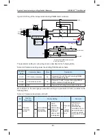
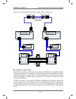
Figure 5-6 Emergency evacuation 220 V UPS circuit
220 VAC
115 VAC
UPS-220 V
UPC
Safety circuit 21
22
Y6
M6
MCB
61
62
21
22
2
1
3
4
R
N
Transformer
115 VDC
220 VAC
UPS-0 V
(6 A)
(6 A)
A1
A2
6
5
14
13
UPC
NICE3000
new
R
S
T
UPC
Note
The UPS emergency evacuation signal can be output only by Y6.
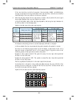
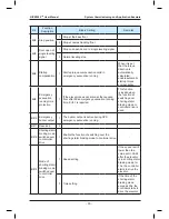
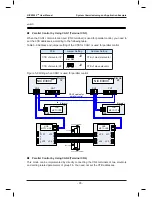
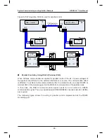
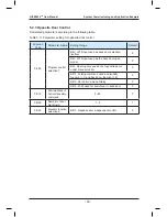
The following figure shows various contacts of the contactors.
Figure 5-7 Various contacts of the contactors
0 V
Safety contactor
A1
A2
53
54
11
14
Phase sequence relay
Safety circuit
UPC
UPC
71
72
21
22
UPC
X20
24 V
Emergency
feedback
UPC
2
1
4
3
6
5 13
14
22
21
54
53
61
62 72
71 81
82
110 V
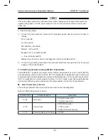
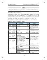
The UPS power is recommended in the following table.
Table 5-4 Recommended UPS power for each power class
UPS Power
Controller Power
1 kVA (700–800 W)
P ≤ 5.5 kW
2 kVA (1400–1600 W)
5.5 kW < P ≤ 11 kW
3 kVA (2100–2400 W)
15 kW ≤ P ≤ 22 kW
Summary of Contents for NICE3000 New
Page 1: ......
Page 13: ......
Page 14: ...1 Safety Information and Precautions ...
Page 21: ...Safety Information and Precautions NICE3000new User Manual 20 ...
Page 22: ...2 Product Information ...
Page 33: ...Product Information NICE3000new User Manual 32 ...
Page 34: ...3 Mechanical and Electrical Installation ...
Page 67: ...4 Use of the NICE3000new ...
Page 79: ...5 System Commissioning and Application Example ...
Page 105: ...6 Function Code Table ...
Page 136: ...Function Code Table NICE3000new User Manual 134 ...
Page 137: ...7 Description of Function Codes ...
Page 205: ...8 EMC ...
Page 214: ...EMC NICE3000new User Manual 212 ...
Page 215: ...9 Troubleshooting ...
Page 230: ......
Page 233: ......

