Engine Mechanical: 1D-1
Engine
Engine Mechanical
Schematic and Routing Diagram
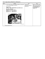
Throttle Cable Routing Diagram
B931H21402001
1
1
2
1
5
5
“B”
3
6
“A”
4
I931H1140114-01
1. Throttle cable
5. Throttle cable guide
2. Brake hose
6. Clamp
3. Handlebar
“A”: Pass through the throttle cable inside of pin.
4. Pin
“B”: Pass through the throttle cable front side of brake hose.
Summary of Contents for 2009 LT-A500XP
Page 2: ......
Page 4: ......
Page 14: ...00 9 Precautions ...
Page 224: ...1E 3 Engine Lubrication System EXHAUST SIDE INTAKE SIDE I931H1150003 02 ...
Page 304: ...1K 4 Exhaust System ...
Page 346: ...2D 5 Wheels and Tires ...
Page 438: ...3D 26 Propeller Shafts ...
Page 482: ...4D 6 Parking Brake ...
Page 512: ...5A 28 Automatic Transmission ...
Page 624: ...Prepared by December 2008 Part No 99500 44080 03E Printed in U S A 624 ...


