Engine Mechanical: 1D-23
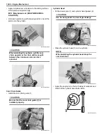
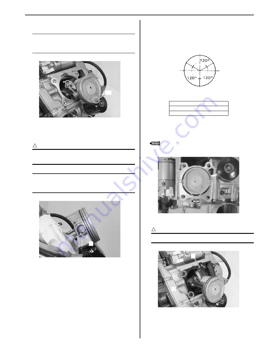
• Install the piston and piston pin.
NOTE
When installing the piston, the indent “A” on
the piston head must be faced to exhaust
side.
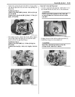
• Place a clean rag over the cylinder base so as not to
drop the piston pin circlips (1) into the crankcase.
• Install the piston pin circlips (1).
CAUTION
!
Use new piston pin circlips (1) to prevent
circlip failure which will occur when it is bent.
NOTE
End gap of the circlip (1) should not be
aligned with the cutaway in the piston pin
bore.
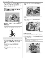
• Position the gaps of the three rings and side rails as
shown in the figure. Before inserting each piston into
the cylinder, check that the gaps are properly
positioned.
Cylinder
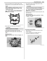
• Apply a bond lightly to the mating surfaces at the
parting line between the left and right crankcases.
: Sealant 99000–31140 (SUZUKI BOND
No.1207B or equivalent)
• Fit the dowel pins (1) and gasket (2).
CAUTION
!
Use the new gasket (2) to prevent oil leakage.
“A”
I931H1140085-01
1
I931H1140086-01
“B”: 2nd ring and lower side rail
“C”: Upper side rail
“D”: 1st ring and spacer
EX.
IN.
“C”
“B”
“D”
I931H1140292-01
I931H1140087-01
1
2
I931H1140088-01
Summary of Contents for 2009 LT-A500XP
Page 2: ......
Page 4: ......
Page 14: ...00 9 Precautions ...
Page 224: ...1E 3 Engine Lubrication System EXHAUST SIDE INTAKE SIDE I931H1150003 02 ...
Page 304: ...1K 4 Exhaust System ...
Page 346: ...2D 5 Wheels and Tires ...
Page 438: ...3D 26 Propeller Shafts ...
Page 482: ...4D 6 Parking Brake ...
Page 512: ...5A 28 Automatic Transmission ...
Page 624: ...Prepared by December 2008 Part No 99500 44080 03E Printed in U S A 624 ...


