Engine Mechanical: 1D-27
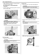
• Apply bond uniformly to the mating surface of the
cylinder head cover and install it within a few minutes.
NOTE
When installing the cylinder head cover, the
piston must be at the top dead center on the
compression stroke.
: Sealant 99000–31230 (SUZUKI BOND
No.1216B or equivalent)
• Apply engine oil to both sides of the washers.
CAUTION
!
Fit the new washer to the bolts (2).
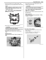
• Lightly tighten the cylinder head cover bolts
diagonally, and then tighten them to the specified
torque.
Tightening torque
Cylinder head cover bolt: 10 N·m (1.0 kgf-m, 7.0
lbf-ft)
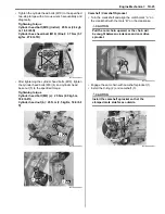
• Apply grease to the O-rings and install the valve
clearance inspection caps.
CAUTION
!
Use the new O-rings to prevent oil leakage.
: Grease 99000–25010 (SUZUKI SUPER
GREASE A or equivalent)
• Tighten the valve clearance inspection cap bolts to the
specified torque.
Tightening torque
Valve clearance inspection cap bolt (a): 10 N·m (
1.0 kgf-m, 7.0 lbf-ft)
Cam Chain Tension Adjuster
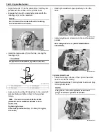
• Apply engine oil to the push rod of the cam chain
tension adjuster.
• Turn the adjusting screw clockwise with a (–)
screwdriver until the push rod locked.
I931H1140104-01
2
I931H1140105-03
(a)
(a)
I931H1140106-01
I931H1140107-01
Summary of Contents for 2009 LT-A500XP
Page 2: ......
Page 4: ......
Page 14: ...00 9 Precautions ...
Page 224: ...1E 3 Engine Lubrication System EXHAUST SIDE INTAKE SIDE I931H1150003 02 ...
Page 304: ...1K 4 Exhaust System ...
Page 346: ...2D 5 Wheels and Tires ...
Page 438: ...3D 26 Propeller Shafts ...
Page 482: ...4D 6 Parking Brake ...
Page 512: ...5A 28 Automatic Transmission ...
Page 624: ...Prepared by December 2008 Part No 99500 44080 03E Printed in U S A 624 ...


