Engine Mechanical: 1D-55
• Tighten the gear position switch mounting bolts.
• Clamp the lead wire firmly.
Oil Jet
Apply engine oil to the O-ring.
CAUTION
!
Use the new O-ring to prevent oil pressure
leak.
Automatic Transmission
Install the automatic transmission component parts (1).
Refer to
“V-belt Type Continuously Variable
Automatic Transmission Removal and Installation:
in Section 5A”
and
“Clutch Shoe Removal and
Installation: in Section 5A”
.
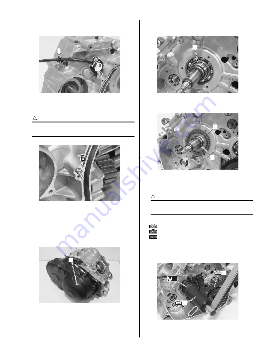
Crank Balancer Drive Gear
• Install the pin (1).
• Install the crank balancer drive gear (2) and washer
(3).
• Hold the crank balancer drive gear with the special
tools and tighten the crank balancer drive gear nut to
the specified torque with the special tool.
CAUTION
!
Do not reuse the crank balancer drive gear
nut.
Special tool
(A): 09920–53740 (Clutch sleeve hub holder)
(B): 09924–52460 (Socket (52 mm))
: 09920–31020 (Extension handle)
Tightening torque
Crank balancer drive gear nut (a): 150 N·m (15.0
kgf-m, 108.5 lbf-ft)
I931H1140223-01
I931H1140224-02
1
I931H1140225-01
1
I931H1140226-01
3
2
I931H1140227-01
(A)
(B)
(a)
I931H1140228-01
Summary of Contents for 2009 LT-A500XP
Page 2: ......
Page 4: ......
Page 14: ...00 9 Precautions ...
Page 224: ...1E 3 Engine Lubrication System EXHAUST SIDE INTAKE SIDE I931H1150003 02 ...
Page 304: ...1K 4 Exhaust System ...
Page 346: ...2D 5 Wheels and Tires ...
Page 438: ...3D 26 Propeller Shafts ...
Page 482: ...4D 6 Parking Brake ...
Page 512: ...5A 28 Automatic Transmission ...
Page 624: ...Prepared by December 2008 Part No 99500 44080 03E Printed in U S A 624 ...


