1D-56 Engine Mechanical:
• Lock the crank balancer drive gear nut with a center
punch.
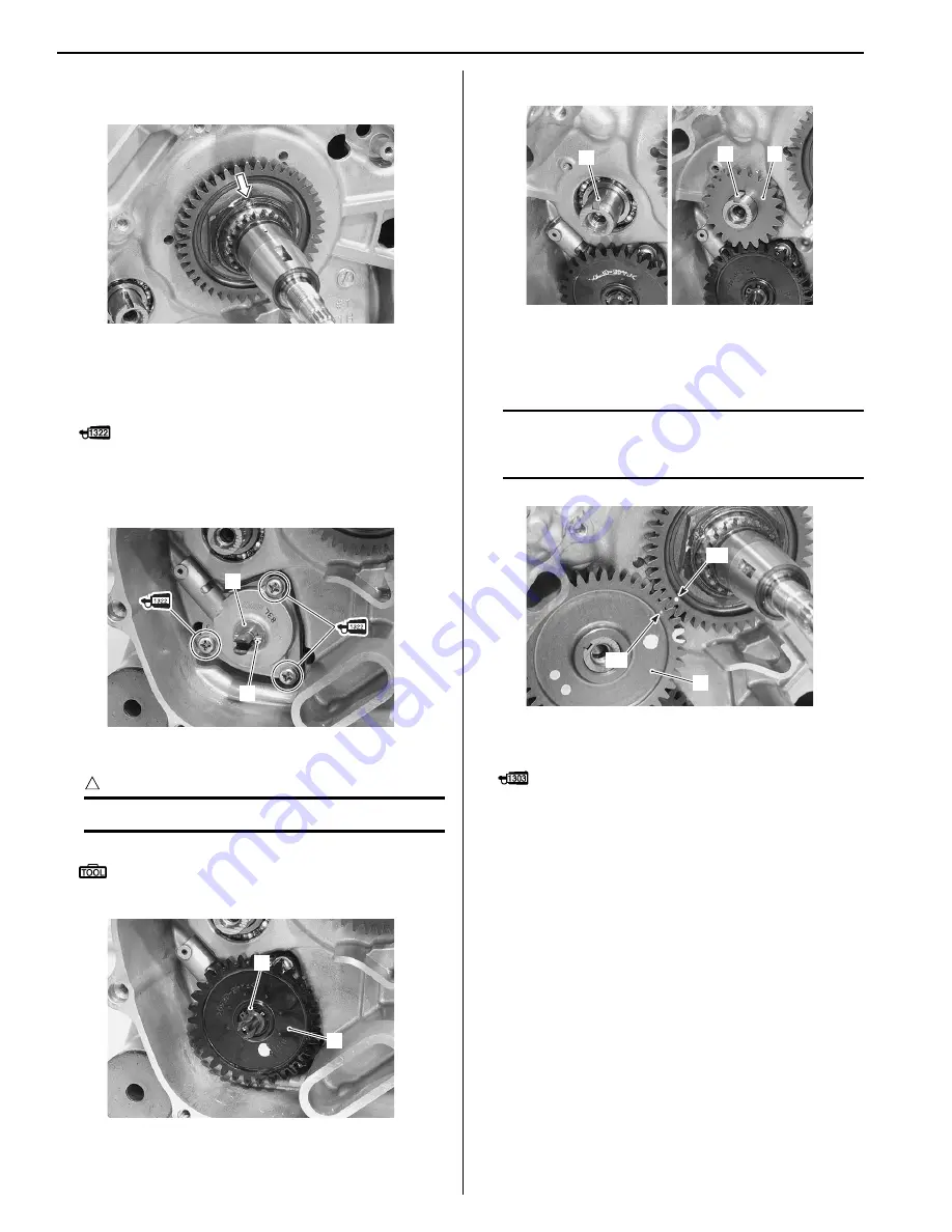
Oil Pump
• Apply thread lock to the oil pump mounting screws
and tighten them.
: Thread lock cement 99000–32110
(THREAD LOCK CEMENT SUPER 1322 or
equivalent)
• Install the washer (1) and pin (2).
• Install the oil pump driven gear (3) and snap ring (4).
CAUTION
!
Never reuse a snap ring (4).
Special tool
: 09900–06107 (Snap ring remover (Open
type))
• Install the key (5) and oil pump drive gear (6).
Crank Balancer Driven Gear
• Install the crank balancer driven gear (1).
NOTE
Align the punch mark “A” of the crank
balancer drive gear with the punch mark “B”
of the crank balancer driven gear (1).
• Apply thread lock to the crank balancer driven gear
bolt.
: Thread lock cement 99000–32030
(THREAD LOCK CEMENT SUPER 1303 or
equivalent)
I931H1140229-01
1
2
I931H1140230-01
4
3
I931H1140231-01
5
5
6
I931H1140233-01
“A”
“B”
1
I931H1140234-01
Summary of Contents for 2009 LT-A500XP
Page 2: ......
Page 4: ......
Page 14: ...00 9 Precautions ...
Page 224: ...1E 3 Engine Lubrication System EXHAUST SIDE INTAKE SIDE I931H1150003 02 ...
Page 304: ...1K 4 Exhaust System ...
Page 346: ...2D 5 Wheels and Tires ...
Page 438: ...3D 26 Propeller Shafts ...
Page 482: ...4D 6 Parking Brake ...
Page 512: ...5A 28 Automatic Transmission ...
Page 624: ...Prepared by December 2008 Part No 99500 44080 03E Printed in U S A 624 ...


