Fuel System: 1G-4
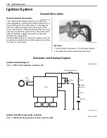
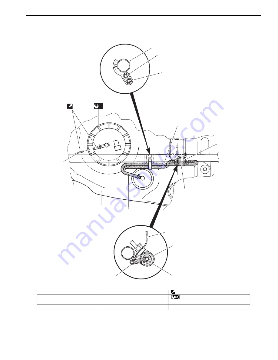
Fuel Tank Breather Hose Routing Diagram
B931H21702002
1
3
2
7
2
3
5
6
4
1
2
6
8
(a)
“A”
I831G1170003-04
1. Frame
5. Valve (Black)
“A”: Align the fuel pump nipple with the mark.
2. Fuel tank breather hose
6. Valve (Orange)
: 35 N
⋅
m (3.5 kgf-m, 25.5 lbf-ft)
3. Check valve hose
7. Mark
4. Fuel tank
8. Fuel tank pressure control valve
Summary of Contents for 2009 LT-A500XP
Page 2: ......
Page 4: ......
Page 14: ...00 9 Precautions ...
Page 224: ...1E 3 Engine Lubrication System EXHAUST SIDE INTAKE SIDE I931H1150003 02 ...
Page 304: ...1K 4 Exhaust System ...
Page 346: ...2D 5 Wheels and Tires ...
Page 438: ...3D 26 Propeller Shafts ...
Page 482: ...4D 6 Parking Brake ...
Page 512: ...5A 28 Automatic Transmission ...
Page 624: ...Prepared by December 2008 Part No 99500 44080 03E Printed in U S A 624 ...


