Drive Chain / Drive Train / Drive Shaft: 3A-4
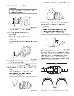
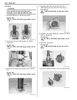
2) Install the cage (1) on the shaft.
CAUTION
!
Install the cage with the large diameter side
“A” facing the shaft end.
3) Install the new snap ring to the cage.
CAUTION
!
Replace the snap ring with a new one.
Special tool
(A): 09900–06107 (Snap ring remover (Open
type))
4) Apply grease to the entire surface of the cage and
the inside of the outer race.
NOTE
The tube of joint grease is included in the
wheel side boot set or wheel side joint
assembly of spare parts.
5) Insert the cage into the outer race and install the new
stopper ring to the groove of the outer race.
CAUTION
!
• Replace the stopper ring with a new one.
• Position the opening of stopper ring “C”
so that it will not be lined up with a ball.
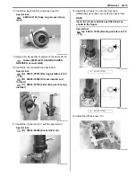
6) After installing the boot on the outer race, insert a
screw driver into the boot on the outer race side and
allow air to enter the boot so that the air pressure in
the boot becomes the same as the atmospheric
pressure at the positions indicated in the figure.
7) Fix the boot on the outer race with a new boot band,
taking care not to distort the boot.
“A”: Large diameter
“B”: Small diameter
Position
Wheel side
Differential side
Grease: Quantity
60 g (2.1 oz)
60 g (2.1 oz)
1
“A”
“B”
I831G1310012-02
(A)
I831G1310023-01
I831G1310013-01
“D”: Right side
“F”: Rotation direction
“E”: Left side
“a”: 182.1 mm (7.2 in)
I831G1310014-01
“C”
I831G1310015-01
A
VIEW A
“F”
“D”
“E”
“F”
“ a ”
I931H1310006-03
Summary of Contents for 2009 LT-A500XP
Page 2: ......
Page 4: ......
Page 14: ...00 9 Precautions ...
Page 224: ...1E 3 Engine Lubrication System EXHAUST SIDE INTAKE SIDE I931H1150003 02 ...
Page 304: ...1K 4 Exhaust System ...
Page 346: ...2D 5 Wheels and Tires ...
Page 438: ...3D 26 Propeller Shafts ...
Page 482: ...4D 6 Parking Brake ...
Page 512: ...5A 28 Automatic Transmission ...
Page 624: ...Prepared by December 2008 Part No 99500 44080 03E Printed in U S A 624 ...


